Jaw crusher and self-travelling crusher

A jaw crusher and crusher technology, which is applied in the direction of motor vehicles, mechanical equipment, screws, etc., can solve the problems of reduced bolt fixing strength, weakened cheek plate installation structure, and shortened bolt life, so as to achieve a firm installation structure and prevent installation. Decrease in strength, effect of preventing abrasion or damage

Inactive Publication Date: 2008-08-27
KOMATSU LTD
View PDF1 Cites 7 Cited by
  • Summary
  • Abstract
  • Description
  • Claims
  • Application Information

AI Technical Summary

Problems solved by technology

[0004] However, during the operation of the jaw crusher, the jaw plate rubs against the raw material, so if the jaw plate is severely worn due to long-term use, the bolts that fit into the recesses of the

Method used


Image

  • Jaw crusher and self-travelling crusher
  • Jaw crusher and self-travelling crusher
  • Jaw crusher and self-travelling crusher

Examples


Embodiment Construction

[0022] [Outline description of the overall configuration]

[0023] Hereinafter, one embodiment of the present invention will be described with reference to the drawings.

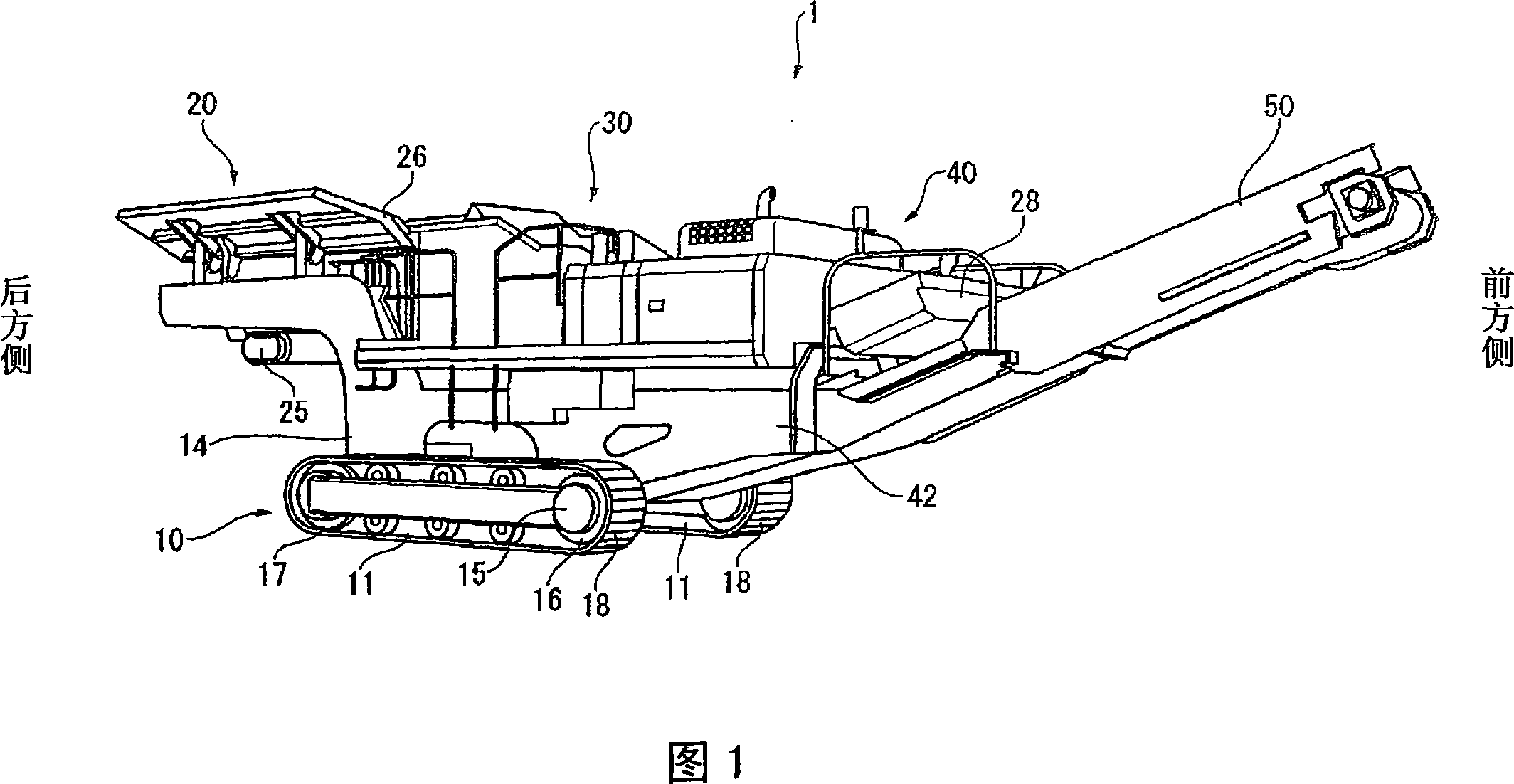
[0024] FIG. 1 is a perspective view showing a self-propelled crusher 1 according to this embodiment. It should be noted that, in this embodiment, for convenience of description, the right side in FIG. 1 is the front side, and the left side is the rear side.

[0025] The self-propelled crusher 1 is composed of a main body unit 10 having a pair of lower traveling bodies 11, a supply unit 20 mounted on the rear side of the main body unit 10 and supplying raw materials, and a jaw type jaw mounted on the front side of the supply unit 20. The crusher 30 , the power unit 40 mounted on the front side of the jaw crusher 30 , and the discharge transport unit 50 extending obliquely forward and upward from between the pair of crawler belts 18 under the main body unit 10 are constituted.

[0026] The main body unit 10 ...


PUM


Abstract

The present invention provides a jaw crusher wherein a teak plate is mounted on the side wall plates of a crusher frame with mounting bolts. The mounting bolts near the outlet of the jaw crusher are formed to be shielded by swing jaws when link mechanisms for adjusting an outlet clearance are adjusted. Since the mounting bolts are covered by the swing jaws while the jaw crusher is operating, a raw material does not touch them, and the mounting bolts can be prevented from being worn or damaged. Accordingly, an increase in the life of the jaw crusher can be promoted. Furthermore, since the mounting bolts can be prevented from being worn or damaged, the mounting structure of the teak plate can be further strengthened.

Description

technical field [0001] The present invention relates to a jaw crusher and a self-propelled crusher having the jaw crusher. Background technique [0002] Conventionally, there is known a jaw crusher that crushes raw materials by swinging a movable jaw relative to a fixed jaw. The fixed jaw and the movable jaw are supported by the crusher frame, and raw materials are put into the area surrounded by the fixed jaw, the movable jaw, and the crusher frame to make the movable jaw swing, thereby crushing the raw material between the fixed jaw and the movable jaw. In the jaw crusher having such a structure, cheek plates are attached to the inner surface of the crusher frame in order to prevent abrasion (for example, refer to Patent Document 1). [0003] Patent Document 1: Japanese Unexamined Patent Publication No. 6-91182 (Fig. 4) [0004] However, during the operation of the jaw crusher, the jaw plate rubs against the raw material, so if the jaw plate is severely worn due to long-...

Claims


Application Information

Patent Timeline
IPC IPC(8): B02C1/02B02C1/04B02C21/02
CPCB02C1/025B02C21/026B02C1/04B02C1/005B02C1/10B02C23/02B62D55/08F16B35/00
Inventor 中山彻富樫良一铃木幸三
Owner KOMATSU LTD
Why Eureka
Try Eureka