

Dishwasher
A dishwashing machine and washing water technology, applied in dishwashing machine/washing machine, dishwashing machine/rinsing washing machine parts, cleaning equipment, etc., can solve problems such as increased cleaning dosage
- Summary
- Abstract
- Description
- Claims
- Application Information
AI Technical Summary
Problems solved by technology
Method used
Image

Examples
Embodiment 1
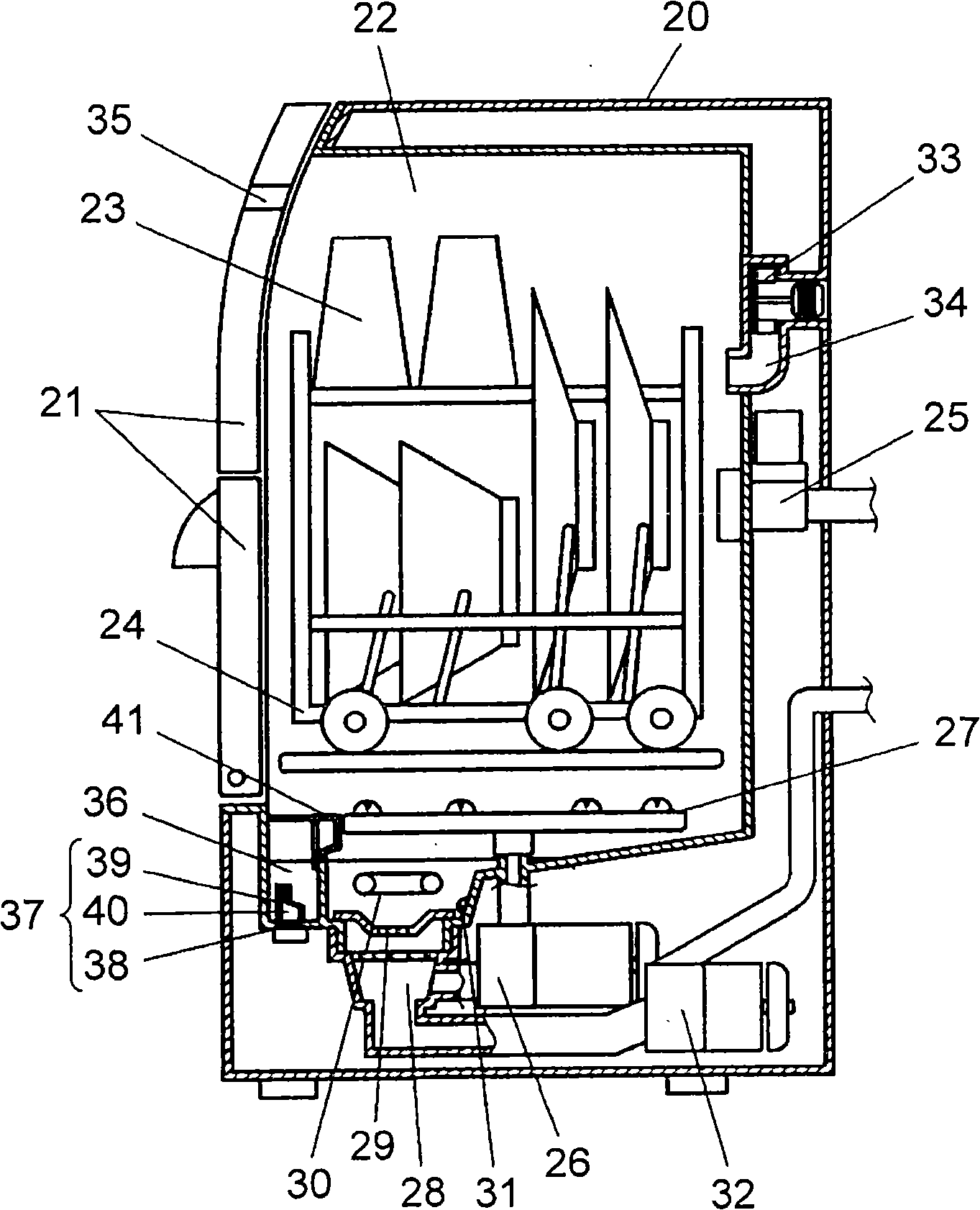
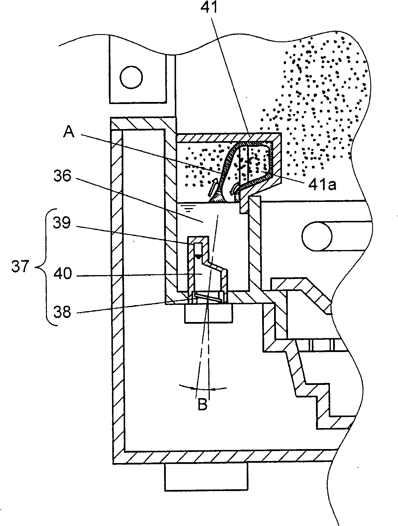
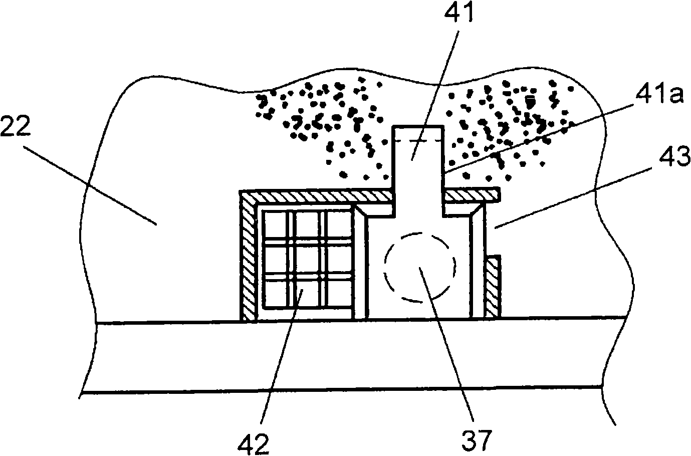
[0069] figure 1 It is a schematic sectional view of a dishwasher provided with a cleaning device in the first embodiment of the present invention, figure 2 A cross-sectional view of its key parts, image 3 A top view of this key part. As shown in these drawings, a washing tank 22 is provided in the body 20 of the dish washing machine, and the washing tank 22 can be opened / closed through a machine door 21, and the objects to be cleaned 23 such as tableware are first placed in the tableware basket 24, and then Put it in the cleaning tank 22. The water inlet valve 25 is used for supplying washing water into the washing tank 22 . The washing pump 26 pressurizes the washing water and supplies it to the plurality of injection holes provided in the washing nozzle 27, and the washing water is sprayed from the washing nozzle 27 to perform the first washing operation. The bottom of the cleaning tank 22 is provided with a drain 28 communicating with the suction side of the cleaning...
Embodiment 2
[0098] Figure 10 Shows a sectional view of key parts of a dishwasher provided with a cleaning device in the second embodiment of the present invention, its basic composition is the same as figure 1 same as in Figure 1 to Figure 9 The same components are marked with the same symbols. Wherein, the cleaning water storage part 36 is completely separated from the cleaning tank 22, and the cleaning water storage part 36 is provided with a second water inlet valve 45 for water intake and a drain valve 46 for water discharge. In addition, the cleaning water storage part 36 is also provided with a cleaning agent dissolving device 47 for stirring the cleaning water to promote the dissolution of the cleaning agent, and a blower device used as a particle scattering device 48 for stirring the scattered fine particles in the cleaning tank 22. .
[0099] During operation, the user first puts cleaning agent in the specified position, and then starts the cleaning operation. After the op...
Embodiment 3
[0106] Figure 11 and Figure 12 It is a cross-sectional view of the key parts of the dishwasher provided with the cleaning device in the third embodiment of the present invention, and its basic composition is the same as figure 1 same as in Figure 1 to Figure 10 The same constituent parts are marked with the same symbols, and the receiving portion 49 adopts another embodiment. Figure 11 Among them, a sink-type receiving portion 49 is provided at the place where the water column falls, and the size of the cleaning water storage portion 36 remains unchanged. Thus, in the process of recovering the washing water into the washing water storage portion 36, the water column A of washing water is not blocked halfway, so that the same operation and effect as in the first embodiment can be obtained. If the water column A is blocked in the middle, the scattering amount of fine particles will be reduced. use Figure 11 With the structure shown in , it is possible to generate more...
PUM
 Abstract
Description
Claims
Application Information