Portable electric tool with braking device

A technology of hand-held machine tools and braking devices, which is applied in the direction of manufacturing tools, electromechanical devices, electric components, etc., and can solve problems such as increasing expenses

Active Publication Date: 2008-09-03
麦太保有限公司
View PDF2 Cites 25 Cited by
  • Summary
  • Abstract
  • Description
  • Claims
  • Application Information

AI Technical Summary

Problems solved by technology

The mechanical coupling is distributed inside

Method used


Image

  • Portable electric tool with braking device
  • Portable electric tool with braking device
  • Portable electric tool with braking device

Examples


Embodiment Construction

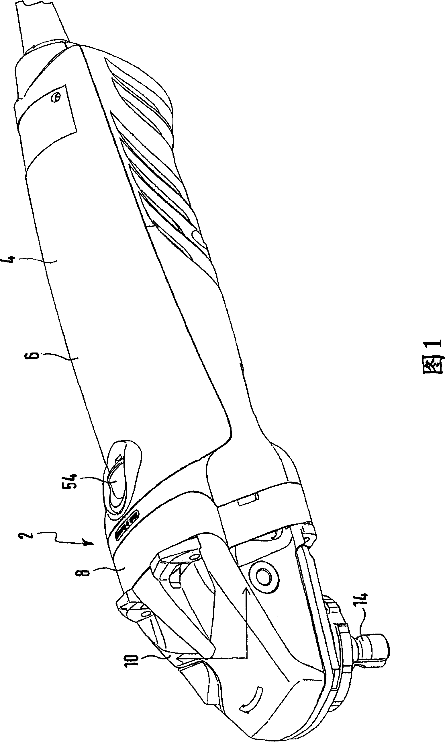
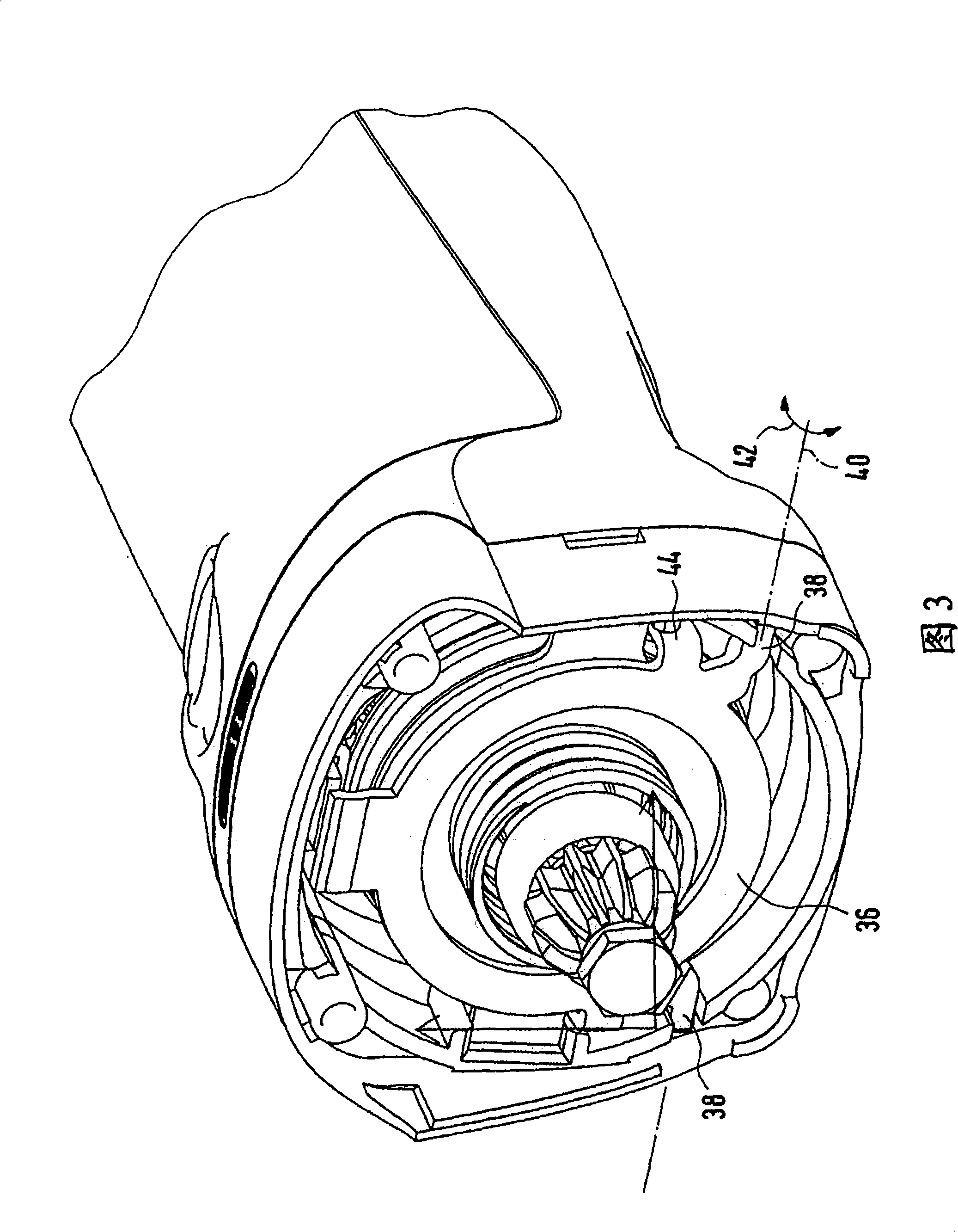
[0025] The figure shows an electric hand-held power tool in the form of a curved handle grinder or a cutting machine marked with the reference numeral 2 as a whole. The machine tool includes a handle part 4 and a transmission mechanism housing part 10, wherein the handle part 4 constitutes the motor housing part 6 at the same time and is connected to the intermediate housing flange 8 which has not been described in detail. The tool spindle 14 is perpendicular to the longitudinal center axis 12 of the machine tool. The ground (see FIG. 4) extends outward from the housing member 10 of the mechanism. A grinding wheel or cutting tool is fixed to the main shaft 14 in a known manner.

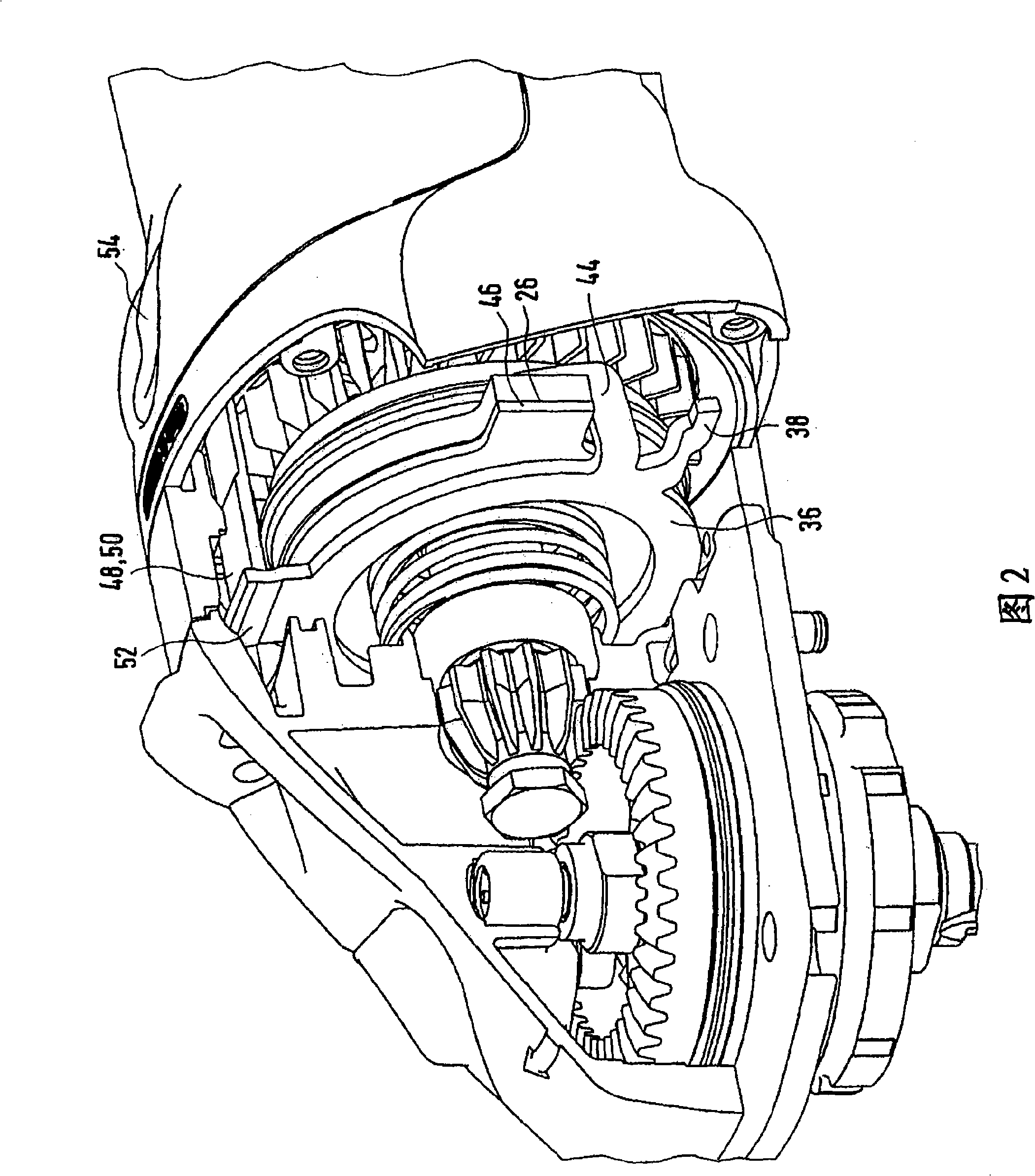
[0026] The transmission shaft 18 extends from the electric motor 16 in the direction 12 of the longitudinal center axis through the intermediate housing flange 8 into the transmission housing part 10. The transmission shaft 18 drives the tool spindle 14 through the bevel gear transmission mechanism 20.

...


PUM

PropertyMeasurementUnit
Axial lengthaaaaaaaaaa

Abstract

The electrical hand tool unit, particularly angle grinder or cut-off grinder, has a drive housing (10), a motor housing part (6) and handle part. A counter-brake disc (26) is moved in release direction from a laminar actuating mechanism (36) extending in a level parallel to the level of the counter-brake disc against the spring pre-tensioning and the laminar actuating mechanism is tilted relative to the earlier level around a certain level.

Description

Technical field [0001] The invention relates to an electric hand-held machine tool, especially a curved handle grinder or a cutting machine, which has a transmission mechanism housing part, a motor housing part and a handle part, wherein at least the transmission mechanism housing part and the motor housing part are separately combined parts with each other , There is also a braking device for braking the drive shaft after the machine tool is disconnected, wherein the braking device is disconnected or reconnected through the mechanical coupling with the manually operable adjustment part of the machine tool, wherein the braking device includes A first brake disc connected to the transmission shaft in a torque-proof connection and a non-rotatable corresponding brake disc, the corresponding brake disc is biased by a spring in the direction of the brake disc. Background technique [0002] Such electric hand-held power tools are known from DE 37 41 536 A1, for example. In this machine...

Claims


Application Information

Patent Timeline
IPC IPC(8): B24B55/00B27B5/38F16D59/02H02K7/102H02P3/04
CPCB24B23/028B24B55/00B27B5/38
Inventor 路德维希·屈特
Owner 麦太保有限公司
Why Eureka
Try Eureka