Method of starting a gas turbine helicopter engine, a fuel feed circuit for such an engine, and an engine having such a circuit

A technology of gas turbines and engines, applied in the direction of machines/engines, gas turbine devices, combustion methods, etc.

Inactive Publication Date: 2008-09-03
TURBOMECA SA
View PDF0 Cites 14 Cited by
  • Summary
  • Abstract
  • Description
  • Claims
  • Application Information

AI Technical Summary

Problems solved by technology

[0005] With this type of fuel line, the head loss caused by the oil level valve 16 is only used to maintain the reserve fuel pressure at start-up, which causes permanent additional pressure in the fuel line when the engine is running

Method used


Image

  • Method of starting a gas turbine helicopter engine, a fuel feed circuit for such an engine, and an engine having such a circuit
  • Method of starting a gas turbine helicopter engine, a fuel feed circuit for such an engine, and an engine having such a circuit
  • Method of starting a gas turbine helicopter engine, a fuel feed circuit for such an engine, and an engine having such a circuit

Examples


Embodiment Construction

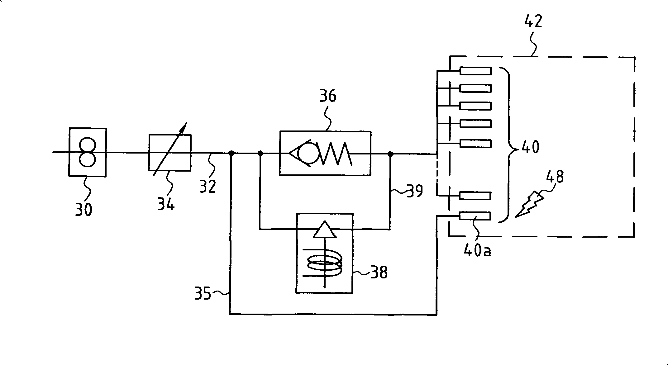
[0022] exist figure 2 In the fuel supply circuit shown, such as figure 1 The circuit shown is the same, and it can be seen that a fuel pump 30 draws fuel from a tank (not shown) and delivers it under pressure through a fuel line 32, which is equipped with a metering valve 34 for regulating fuel oil. flow.

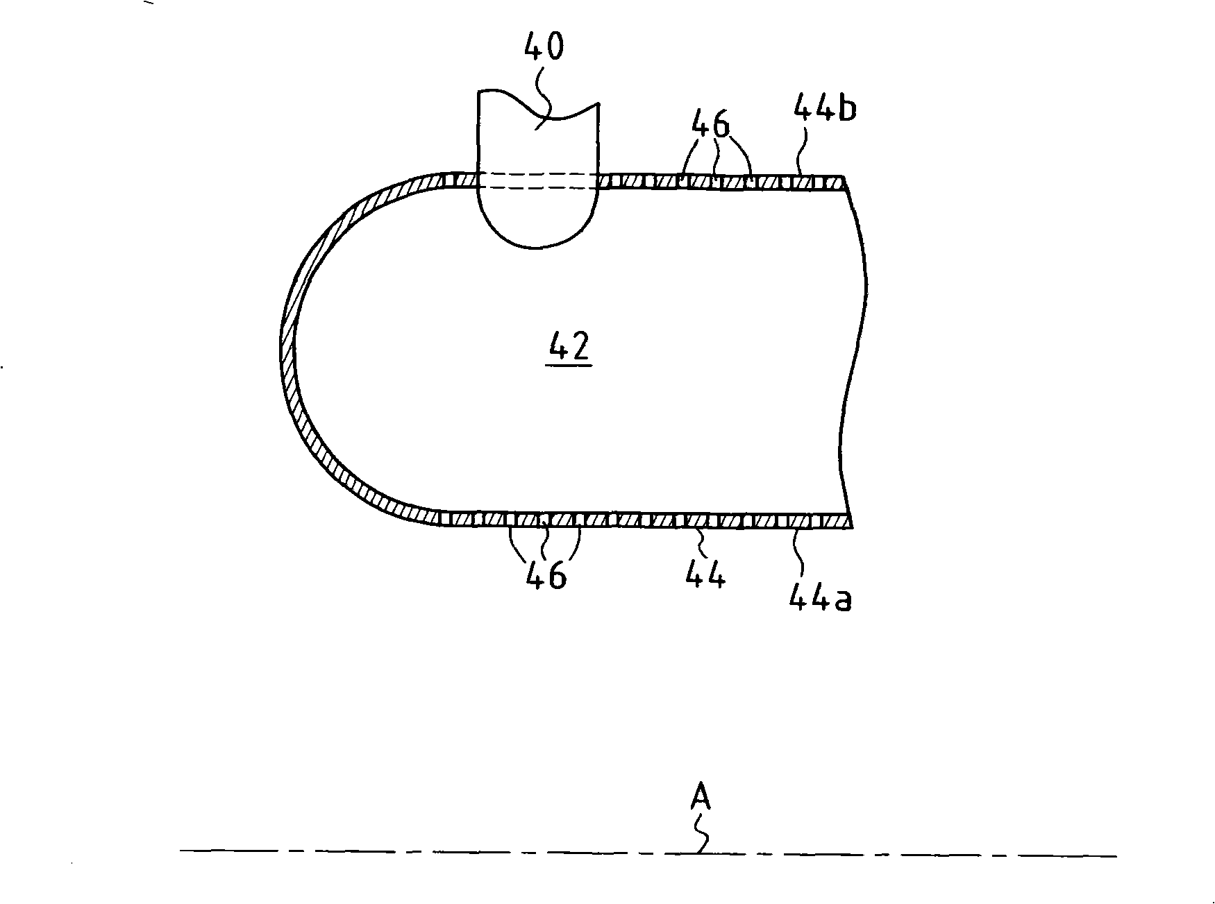
[0023] A plurality of main injectors 40 are mounted on the walls of the combustion chamber 42 to inject an air and fuel mixture into the combustion chamber. One of the main injectors 40 a is directly connected to the fuel line 32 through a line 35 . The other main injectors are connected to the fuel line 32 by a circuit comprising a rated flow holding valve or level valve 36 mounted in parallel, and an on / off valve 38 mounted on a line 39 from Passing beside the oil level valve 36 , the pipe 35 is connected to the fuel line 32 upstream of the oil level valve 36 . The oil level valve 36 applies a pre-regulated head loss - eg - 6 bar to 10 bar (0.6 MPa to 1 MPa) via a sp...


PUM


Abstract

The present invention provides a method of starting a gas turbine helicopter engine. At least one of the main injectors of the engine, forming a starter main injector, is fed directly by the pressurized feed pipe, while a head loss is imposed between the pressurized feed pipe and the other main injectors. Ignition is caused to take place at the starter main injector, and after ignition, said head loss imposed between the feed pipe and the other main injectors is eliminated so that all of the main injectors are fed with fuel at substantially the same pressure, without any imposed head loss. The present invention also provides a fuel supply circuit for such an engine, and engine having such a circuit.

Description

technical field [0001] The present invention relates to a helicopter gas turbine engine, in particular to the fuel supply of the engine, and in particular to the starting method of the engine. Background technique [0002] figure 1 Shown is a known fuel circuit commonly used to deliver fuel to helicopter engine combustors. [0003] The fuel pump 10 extracts the fuel from the fuel tank (not shown in the figure), and delivers the fuel under pressure through the fuel pipe 12, and a metering valve 14 is installed on the fuel supply pipe to regulate the fuel flow. Fuel line 12 is connected through a rated flow maintaining valve 16 , or level valve, to a set of main injectors 20 which are used to inject an air and fuel mixture into combustion chambers 22 . The oil level valve 16 adds a head loss of - for example - 6 bar to 10 bar (0.6 MPa to 1 MPa), the pressure being adjusted by a spring. At a location upstream of the fuel level valve 16, the fuel line 12 is also connected to ...

Claims


Application Information

Patent Timeline
Patent Type & Authority Applications(China)
IPC IPC(8): F02C7/264F02C7/22F23R3/28
CPCF02C7/264F01D17/00
Inventor 于贝尔·韦迪尔
Owner TURBOMECA SA
Why Eureka
Try Eureka