Al technical title is built by PatSnap Al team. It summarizes the technical point description of the patent document.
A range hood and blower technology, applied in the field of range hoods, to achieve the effects of low turbulence formation probability, good range hood effect, and large suction force
Active Publication Date: 2008-09-03
吴运良
View PDF0 Cites 3 Cited by
Summary
Abstract
Description
Claims
Application Information
AI Technical Summary
This helps you quickly interpret patents by identifying the three key elements:
Problems solved by technology
Method used
Benefits of technology
Problems solved by technology
[0002] At present, the known side-suction type, oblique side-type household range hoods and commercial range hoods are all radial-flow side-inlet structural forms, and the separated oil fume airflow is as follows: Figure 1~4 As shown, before entering the air inlet, it forms a large area of disordered turbulent flow with the space below the centerline of the volute; between the front of the air inlet and the wall of the air duct, the two lower corners of the 60-80mm air inlet and the air inlet The upper area accounts for 50-59% of the total volume of the air inlet duct, forming a disorderly turbulent space; when the separated oily fume flow enters the inner cavity along the direction perpendicular to the impeller inlet, the air flow aligns with the impeller lock nut and the raised area, forming Disordered turbulent flow; the total loss accounts for 3-5% of the total power
Method used
Image
Click on the blue label to locate the original text in one second.
Reading with bidirectional positioning of images and text.
Examples
Embodiment 1
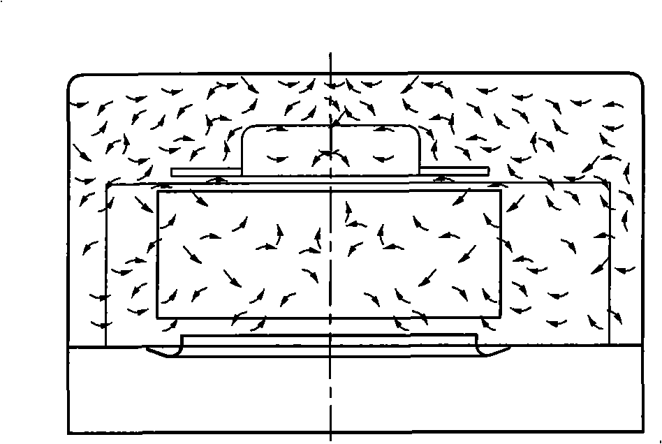
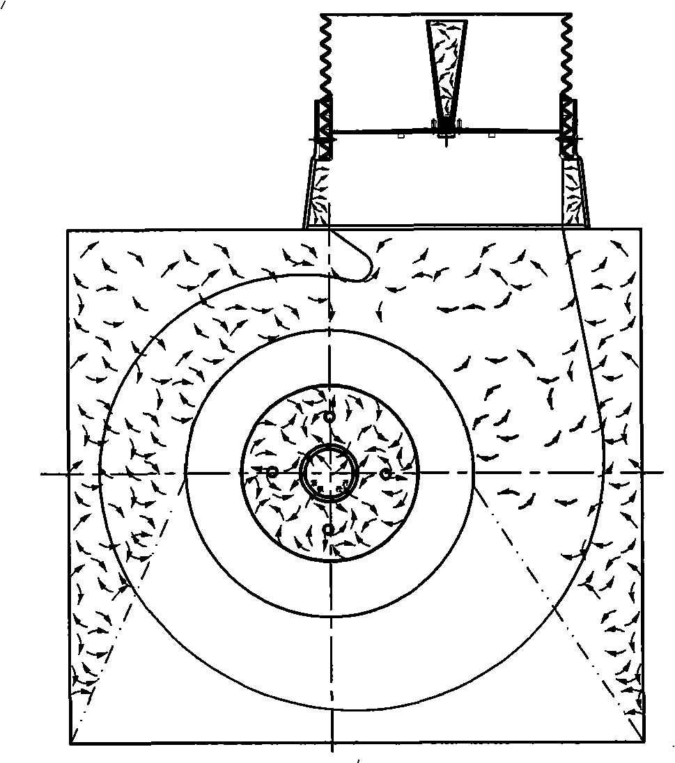
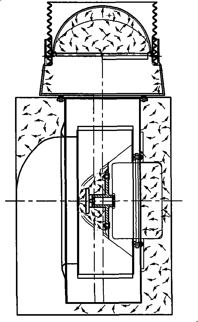
[0029] Depend on Figure 5-8 It can be seen that the rectifying air cylinder used by the rear air intake type range hood is composed of the following parts.
[0030] 1 air cylinder cover, 2 air cylinder, 3 upper cover, 4 valve plate, 5 intake deflector, 6 deflector cover, 7 volute, 8 conical deflector nut, 9 motor, 10 impeller, 11 exhaust Section, 12 air inlet section, 13 throat, 14A node, 15B node, 16C node, 17 wall hook, 18 smoke hood, 19 panel, 20 volute side plate, 21 connecting cylinder, 22 flue base plate, 23 volute Air inlet side panel, 24 separators, 25 left panel, 26 right panel.
[0031] The smoke collecting hood of the rectifying air duct used in the range hood is provided with an air duct, which is a rectangular duct and consists of a flue base plate 22, an upper cover 3, a left side plate 25, a right side plate 26 and a volute side plate 20. .
[0032] In the blower, the motor 9 is connected to the volute side plate 20, and the impeller 10 mounted on its shaft ...
Embodiment 2
[0037] Depend on Figures 9 to 12 It can be seen that the rectifying air duct used for the range hood of the forward air type is the same as that of Example 1.
[0038] Wherein the air intake deflector 5 is inclined to the air intake direction, and the included angle with the flue base plate 22 is 120°.
PUM
Abstract
A rectifying wind barrel of a cooker hood is provided with a rectangular shape, comprising a fume canal base plate, an upper cover, a left side plate, a right side plate and a turbine housing. An electric motor is fastened on the turbine housing side plate of the rectifying wind barrel, a blade wheel which is covered by the turbine housing is disposed on the electric motor shaft, and a fume rectifying part is disposed in the wind barrel. The rectifying wind barrel rectifies fume by the fume rectifying part, and a wind inlet flow guiding plate is disposed at the initial position; a flow guiding cover is disposed at the upper segment of the fume canal formed by a turbine housing wind inlet side plate and the fume canal base plate; the throat portion of the fume canal outlet is formed by sequentially connecting a wind discharging segment and a wind charging segment of the turbine casing wall, and the turbine housing wind inlet side plate, the wind discharging segment of the turbine housing changes to a curve surface from the housing wall horizontal center, the wind charging segment of the turbine housing wall changes to a curve surface from a folding point upwards, the part of the turbine housing wind inlet side plate adjacent to the throat portion changes to a curve surface from the horizontal center; and a valve sheet protrudes in the connection barrel on the wind outlet throat portion. The invention is provided with a simple structure, big extraction force, energy saving little turbulent current forming probability.
Description
technical field [0001] The invention belongs to the technical field of range hoods, in particular to a rectifying air cylinder used for range hoods to reduce smoke turbulence. Background technique [0002] At present, the known side-suction type, oblique side-type household range hoods and commercial range hoods are all radial-flow side-inlet structural forms, and the separated oil fume airflow is as follows: Figure 1~4 As shown, before entering the air inlet, it forms a large area of disordered turbulent flow with the space below the centerline of the volute; between the front of the air inlet and the wall of the air duct, the two lower corners of the 60-80mm air inlet and the air inlet The upper area accounts for 50-59% of the total volume of the air inlet duct, forming a disorderly turbulent space; when the separated oily fume flow enters the inner cavity along the direction perpendicular to the impeller inlet, the air flow aligns with the impeller lock nut and the rais...
Claims
Application Information
Patent Timeline
Application Date:The date an application was filed.
Publication Date:The date a patent or application was officially published.
First Publication Date:The earliest publication date of a patent with the same application number.
Issue Date:Publication date of the patent grant document.
PCT Entry Date:The Entry date of PCT National Phase.
Estimated Expiry Date:The statutory expiry date of a patent right according to the Patent Law, and it is the longest term of protection that the patent right can achieve without the termination of the patent right due to other reasons(Term extension factor has been taken into account ).
Invalid Date:Actual expiry date is based on effective date or publication date of legal transaction data of invalid patent.