
System and process for utilizing back electromotive force in disk drives

a technology of electromotive force and system, applied in the direction of motor/generator/converter stopper, electronic commutator, dynamo-electric converter control, etc., can solve the problem that the rotor in the turning motor cannot come to a complete stop in a short amount of time, and the head and/or data media may be damaged, etc. problems, to achieve the effect of effectively and reliably using back electromotive force voltag

Inactive Publication Date: 2008-02-05
MARVELL ASIA PTE LTD
View PDF25 Cites 4 Cited by
  • Summary
  • Abstract
  • Description
  • Claims
  • Application Information

AI Technical Summary

Benefits of technology

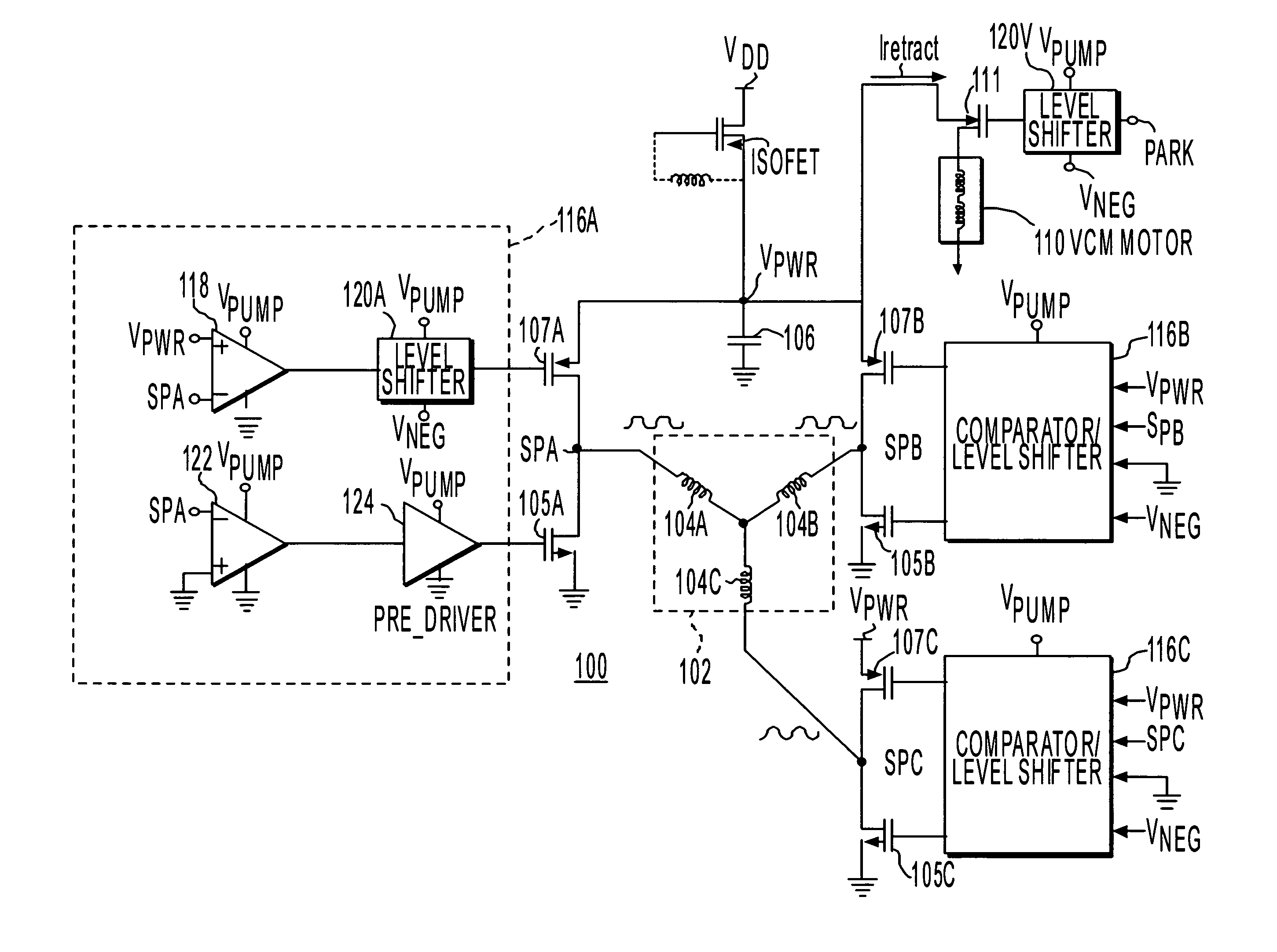
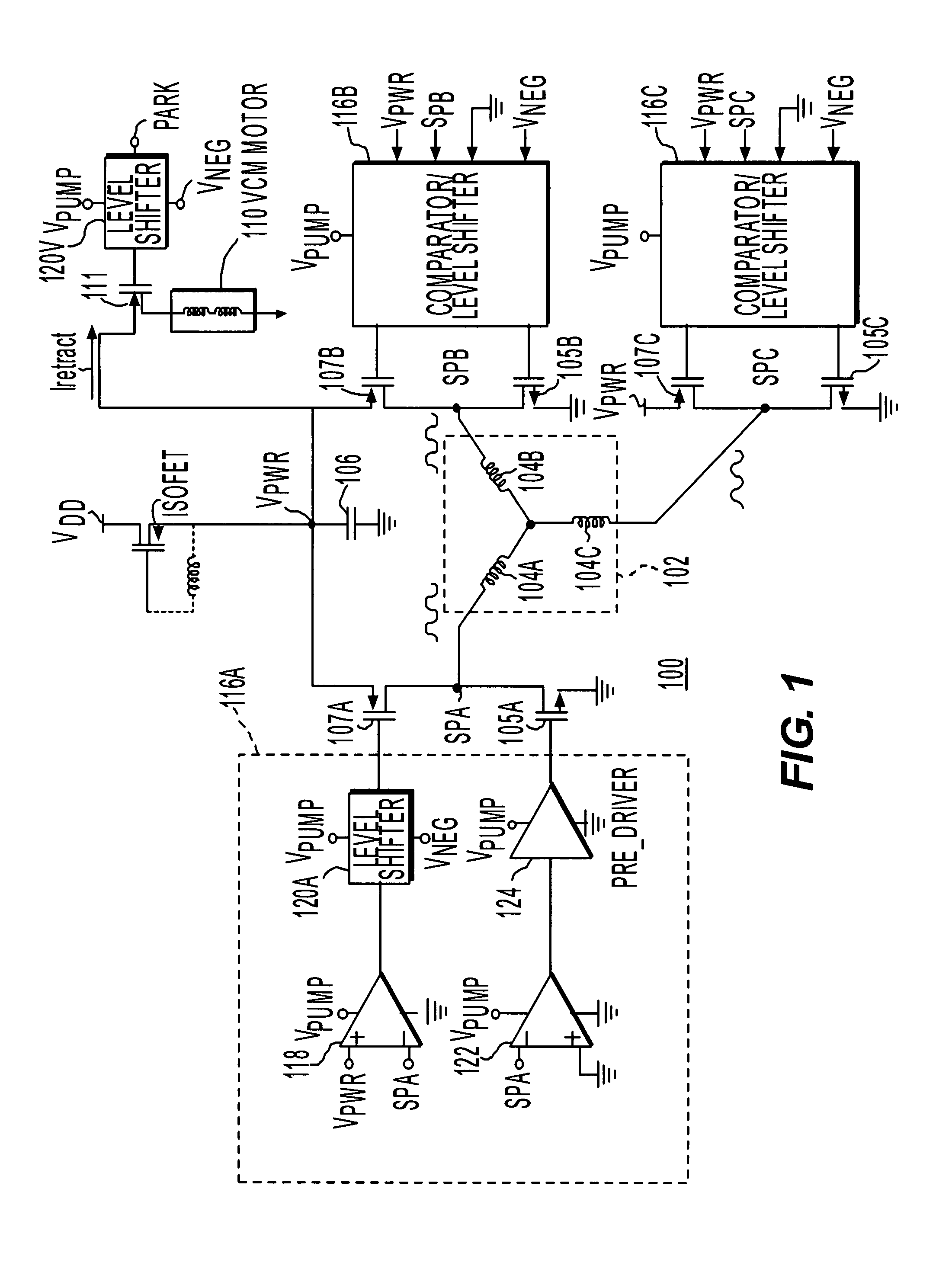
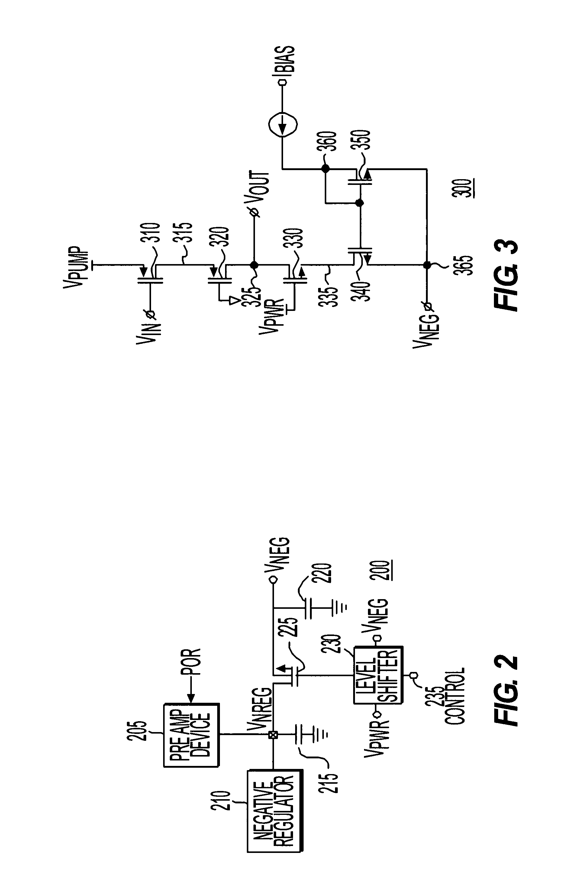
The invention provides a system and method for effectively and reliably using back electromotive force (BEMF) voltage to power another device, such as a motor, when a motor is not receiving power. The system includes a switching circuit with multiple switches and a controller for controlling the switches. The controller receives a BEMF voltage and shifts it to a level shifted voltage to control the switches. The system can be used in disk drives and other applications where BEMF voltage is needed to power a device. The technical effect of the invention is to provide a more efficient and reliable way to use BEMF voltage for powering devices.

Problems solved by technology

Further, the read / write head motor for extending and retracting the read / write head is also without power.
If the data media stops turning with the read / write head extended over it, the head and / or data media may be damaged.
Even during a power failure, it generally takes a short amount of time for the rotor in the turning motor to come to a complete stop due to inertia and residual forces.
However, when the available BEMF voltage from the spindle motor is of the order or less than the threshold voltage of a transistor, such as a standard complementary metal-oxide semiconductor (“CMOS”) transistor or a positive channel metal oxide semiconductor transistor, the driver transistors often cannot be turned on, or will provide a large on resistance when providing current to a device, such as the motor that retracts the read / write head.

Method used


Image

  • System and process for utilizing back electromotive force in disk drives
  • System and process for utilizing back electromotive force in disk drives
  • System and process for utilizing back electromotive force in disk drives

Examples


Embodiment Construction

[0023]The embodiments of the invention and the various features and advantageous details thereof are explained more fully with reference to the non-limiting embodiments and examples that are described and / or illustrated in the accompanying drawings and detailed in the following description. It should be noted that the features illustrated in the drawings are not necessarily drawn to scale, and features of one embodiment may be employed with other embodiments as the skilled artisan would recognize, even if not explicitly stated herein. Descriptions of well-known components and processing techniques may be omitted so as to not unnecessarily obscure the embodiments of the invention. The examples used herein are intended merely to facilitate an understanding of ways in which the invention may be practiced and to further enable those of skill in the art to practice the embodiments of the invention. Accordingly, the examples and embodiments herein should not be construed as limiting the s...


PUM


Abstract

A circuit system and process utilizes back electromotive force (BEMF) voltage to assist in safe power down of devices, such as the read / write head in from low factor disk drives or similar devices. The BEMF voltage from a motor device, such as a spindle motor utilized in a circuit using negative voltage to drive some switches, such as positive channel metal oxide semiconductor (“PMOS”) driver transistors, to reduce and / or effectively minimize the on-resistance of the switches while delivering the current from BEMF voltage of the motor to another device, such as a motor that retracts controls a read / write head.

Description

CROSS REFERENCE TO RELATED APPLICATIONS[0001]This application claims priority under 35 U.S.C. § 120(c) to U.S. application Ser. No. 11 / 179,593, filed on Jul. 13, 2005 now U.S. Pat. No. 7,211,973, which claims priority to U.S. Provisional Application Ser. No. 60 / 643,026, filed on Jan. 7, 2005, and U.S. Provisional Application Ser. No. 60 / 687,447 filed on Jun. 6, 2005, the disclosure of which is expressly incorporated by reference herein in its entirety.BACKGROUND[0002]1. Field of the Invention[0003]The invention relates generally to a system and process for utilizing electromotive force and, more particularly, to a system and process for utilizing back electromotive force voltage from low factor disk drives and similar devices.[0004]2. Related Art[0005]Disk drives, including low form factor disk drives such as those of a diameter of 1.8″ and below, use a motor to rotate the data media at high rates. Another motor, typically a voice coil motor (“VCM”), is used in disk drives to extend...

Claims


Application Information

Patent Timeline
Patent Type & Authority Patents(United States)
IPC IPC(8): H02P1/18
CPCG11B21/12
Inventor HOO, LEGAL REPRESENTATIVE, KUONGKUMAR, VISHNUCHUI, SIEW YONGRANA, DECEASED, SAKTI PADA
Owner MARVELL ASIA PTE LTD
Learn More