Heat radiating module

A technology of heat dissipation module and heat dissipation unit, which is applied in cooling/ventilation/heating transformation, instruments, electrical and digital data processing, etc.

Active Publication Date: 2009-01-14
ASUSTEK COMPUTER INC
View PDF0 Cites 4 Cited by
  • Summary
  • Abstract
  • Description
  • Claims
  • Application Information

AI Technical Summary

Problems solved by technology

However, since the notebook computers currently on the market are all developing toward thinner and lighter, and the internal space of the notebook computer is limit

Method used


Image

  • Heat radiating module
  • Heat radiating module
  • Heat radiating module

Examples


Embodiment Construction

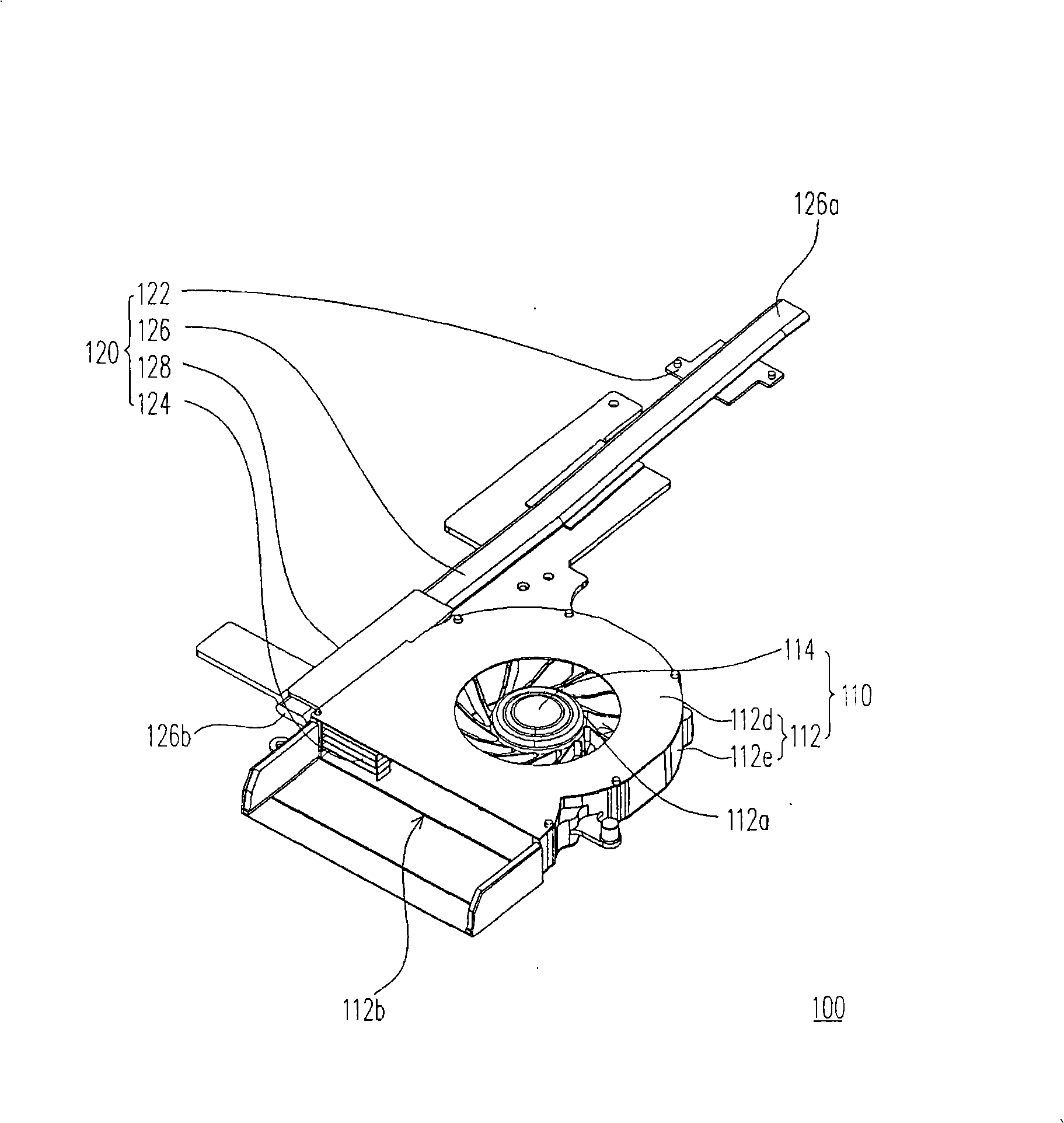
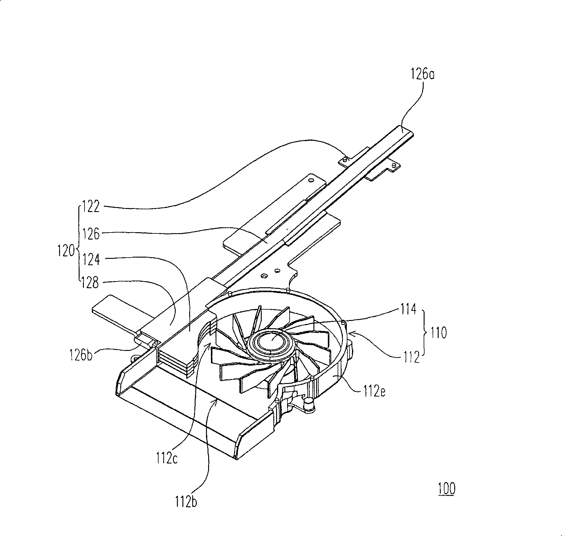
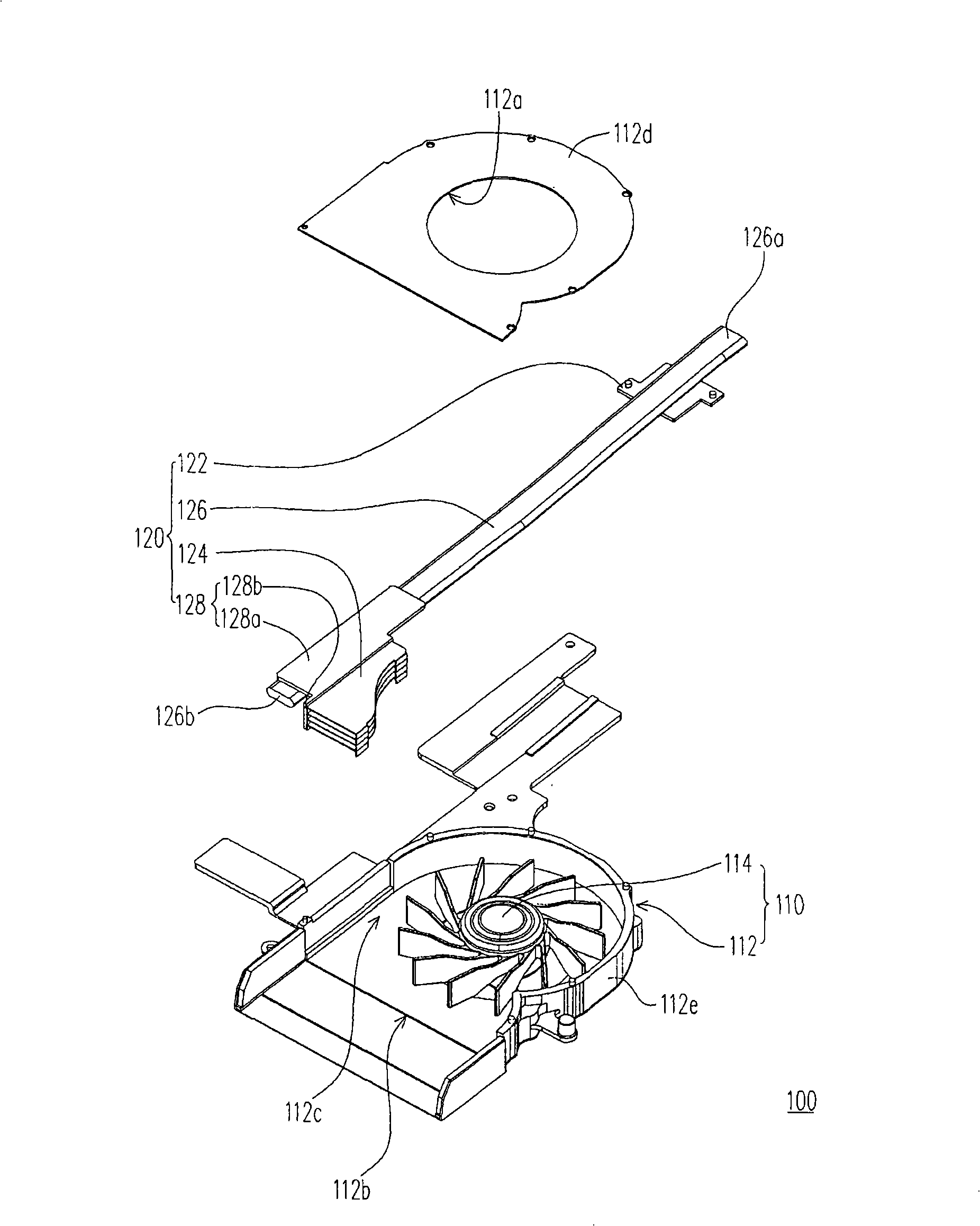
[0022] Figure 1A Shown is a perspective view of a heat dissipation module according to an embodiment of the present invention, Figure 1B shown as Figure 1A The schematic diagram of the heat dissipation module after removing the upper cover of the frame, while Figure 1C shown as Figure 1A Partial exploded view of the cooling module. Please also refer to Figure 1A , Figure 1B as well as Figure 1C , the heat dissipating module 100 of this embodiment is suitable for dissipating heat from an electronic device such as a notebook computer. Specifically, since the notebook computer is equipped with a central processing unit (CPU), a northbridge chip (northbridge chip), a southbridge chip (south bridge chip) or other devices that generate a large amount of heat in the working state chip, and the heat dissipation module 100 of this embodiment is suitable for disposing on the above-mentioned heat generating chip, so as to effectively dissipate heat from the chip, and further e...


PUM


Abstract

A heat dissipation module comprises a fan and a first heat dissipation unit, wherein, the fan is provided with a frame body and a fan leaf group arranged in the frame body; the frame body is provided with an air inlet and an air outlet; a flow channel communicated with the air inlet and the air outlet is formed between the fan leaf group and the frame body; the first heat dissipation unit comprises a first heat dissipation seat, a first heat dissipation fin group arranged at the internal wall of the frame body and positioned above the flow channel, and a first heat pipe connected between the first heat dissipation seat and the first heat dissipation fin group.

Description

technical field [0001] The present invention relates to a heat dissipation module, and in particular to a heat dissipation module of a notebook computer. Background technique [0002] In recent years, with the rapid development of computer technology, the operating speed of the computer has been continuously improved, and the heating power of the electronic components inside the computer body has also been continuously increased. In order to prevent the electronic components inside the computer body from overheating, resulting in temporary or permanent failure of the electronic components, how to dissipate heat from these electronic components is an important issue. [0003] Taking a notebook computer as an example, the conventional technology usually installs a fan in the body of the notebook computer, and arranges a heat dissipation fin group connected with the electronic components outside the air outlet of the fan, so that the airflow generated by the fan can The heat c...

Claims


Application Information

Patent Timeline
IPC IPC(8): G06F1/20H05K7/20
Inventor 萧名扬
Owner ASUSTEK COMPUTER INC
Why Eureka
Try Eureka