Charging method and charging device for fixed air-quantity temperature difference type central air-conditioning
A technology for central air-conditioning and billing devices, applied to measuring devices, billing equipment, calorimeters, etc., can solve problems such as reducing energy consumption, prolong the service life of equipment, improve the value of promotion and application, and achieve accurate heat exchange effects Effect
- Summary
- Abstract
- Description
- Claims
- Application Information
AI Technical Summary
Problems solved by technology
Method used
Image
Examples
Embodiment 1
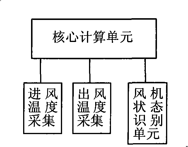
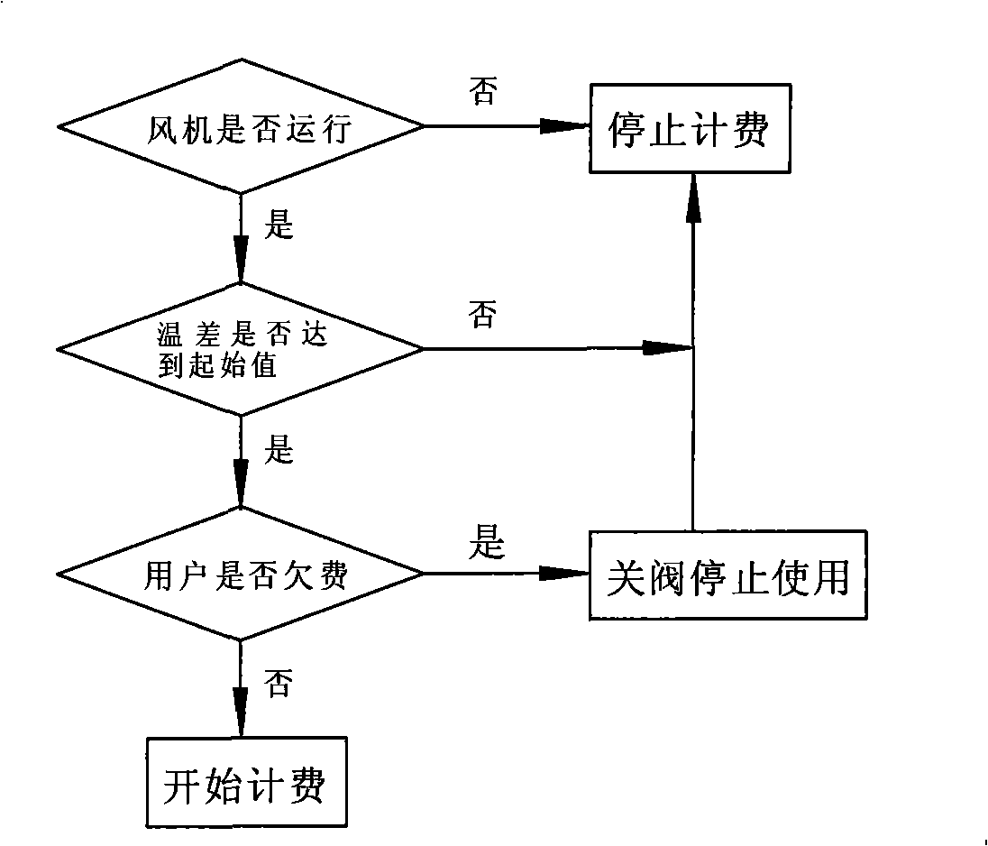
[0056] Example one: see figure 1 , figure 2 , The charging method of the fixed air volume temperature difference type central air conditioner of the present invention, for each billing unit of the same central air-conditioning system, install temperature sensors at the air conditioning inlet and outlet of the user of the billing unit to collect the temperature of the inlet and outlet at the same time. The fan status recognition device detects the different gear status of the air conditioner fan, and the charging method realizes the on-demand charging of the central air conditioner through the following steps:
[0057] (1) First, set the wind speed of a certain gear state of the user's air-conditioning fan to a corresponding predetermined value ki,
[0058] (2) In the case of detecting the operation of the fan, judge whether the temperature difference between the inlet and outlet of the air conditioner reaches a preset initial value,
[0059] (3) When the temperature difference b...
Embodiment 2
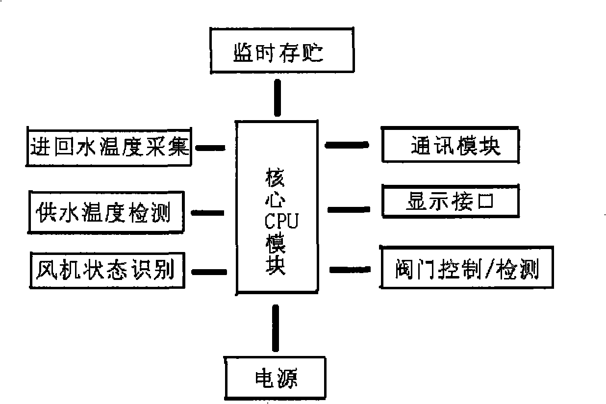
[0066] Embodiment 2: This embodiment is a specific implementation of the charging device of the present invention. For the configuration of the charging device unit module, see figure 1 , The charging device contains a core computing unit, as well as a peripheral temperature acquisition unit and a fan operating state identification unit. image 3 Schematic diagram of the functional modules of the core computing unit. In the figure, U1 is the CPU, U2 is the time monitoring memory, and U3 is the uplink communication RS485 bus communication chip.
[0067] See Figure 4 , Figure 6 , The central processor in the core CPU module uses 89S52, or any one of AT89C52, P89C54BP, P89C58A, MC68HC11A8, MC68HC11E9, MC68HC16, PIC16C877A, EM78P447, MSP430F147, MSP430F435, E78C52D, E78E58B and subsequent compatible chips. The four I / O ports of the CPU are respectively connected to the corresponding interfaces WDOG, W_SO, W_CLK, W_DATA of the time monitoring storage module. These interfaces can be ...
Embodiment 3
[0071] Embodiment 3: Refer to the specific circuit Figure 4 ~ Figure 11 , Figure 17 . The device has an on-site display module. The difference from the second embodiment is that the user does not install a door-in valve, and the valve control / detection module controls the power circuit of the fan to realize the prohibition of arrears.
PUM
 Abstract
Description
Claims
Application Information
 - R&D
- Intellectual Property
- Life Sciences
- Materials
- Tech Scout
- Unparalleled Data Quality
- Higher Quality Content
- 60% Fewer Hallucinations
Browse by: Latest US Patents, China's latest patents, Technical Efficacy Thesaurus, Application Domain, Technology Topic, Popular Technical Reports.
© 2025 PatSnap. All rights reserved.Legal|Privacy policy|Modern Slavery Act Transparency Statement|Sitemap|About US| Contact US: help@patsnap.com


