

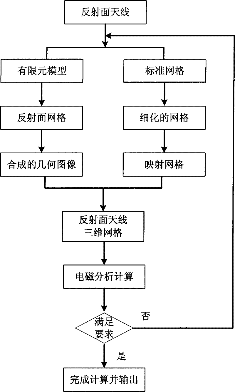
Method for dividing aerial reflecting plane graticule based on structure electromagnetic coupling
A grid division and electromagnetic coupling technology, applied in the direction of antennas, electrical components, etc., to achieve the effect of solving disconnection, improving calculation speed, and accurate analysis and calculation
- Summary
- Abstract
- Description
- Claims
- Application Information
AI Technical Summary
Problems solved by technology
Method used
Image

Examples
example 1
[0102] A rotating parabolic antenna with a diameter of 30m and a working frequency of 2G is used. The reflecting surface is composed of 108 rectangular panels, the reflecting surface is divided into 18 equal parts in the ring direction and 6 equal parts in the radial direction, and the focal diameter ratio is 0.5. Apply professional electromagnetic analysis software FEKO, and use physical optics method for calculation.
[0103] The structural analysis finite element model of the reflector antenna is as Figure 5 As shown, the reflective surface mesh extracted from it is as Picture 12 Shown.
[0104] Use the existing grid division method and the method of the present invention to grid the rotating parabolic antenna, and calculate its antenna pattern, such as Figure 13 , Figure 14 with Figure 15 Shown. The calculation results of the three directional patterns are compared, as shown in Table 1.
[0105] Table 1
[0106] Meshing
Corresponding pattern
Number of triangles
calcu...
example 2
[0111] A parabolic cylindrical antenna with a diameter of 4m, a width of 10m, and a working frequency of 1G is used.
[0112] The reflecting surface is composed of 160 triangular panels. The aperture direction of the reflecting surface is divided into 8 equal parts and the width direction is divided into 10 equal parts. The focal diameter ratio of the parabola is 0.5. The reflecting surface net is extracted from the structural analysis finite element model of the reflecting surface antenna. Geru Figure 16 Shown.
[0113] Apply professional FEKO software and use physical optics to calculate. Use the existing grid division method and the method of the present invention to grid the parabolic cylindrical antenna, and calculate its antenna pattern, such as Figure 17 , Figure 18 with Figure 19 Shown. The calculation results of the three directional patterns are compared, as shown in Table 2.
[0114] Table 2
[0115] Grid model
Corresponding pattern
Number of triangles
calcula...
PUM
 Abstract
Description
Claims
Application Information