
Motor control circuit and method as well as brushless motor system

A motor control and circuit technology, applied in the field of motor control circuits, brushless motor systems, and motor control methods, can solve the problems of inconvenience, general products and methods without suitable structures and methods, etc.

Active Publication Date: 2008-09-03
PROLIFIC TECH INC
View PDF5 Cites 10 Cited by
  • Summary
  • Abstract
  • Description
  • Claims
  • Application Information

AI Technical Summary

Problems solved by technology

[0024] It can be seen that the above-mentioned existing motor control method, motor control circuit and brushless motor system obviously still have inconvenience and defects in product structure, control method and use, and need to be further improved urgently.
In order to solve the above-mentioned problems, the relevant manufacturers have tried their best to find a solution, but no suitable design has been developed for a long time, and there is no suitable structure and method for general products and methods to solve the above-mentioned problems. This is obviously a problem that relevant industry players are eager to solve

Method used


Image

  • Motor control circuit and method as well as brushless motor system
  • Motor control circuit and method as well as brushless motor system
  • Motor control circuit and method as well as brushless motor system

Examples


Embodiment Construction

[0088] In order to further explain the technical means and effects of the present invention to achieve the intended purpose of the invention, in conjunction with the accompanying drawings and preferred embodiments, the specific implementation methods, Structure, method, step, feature and effect thereof are as follows in detail.

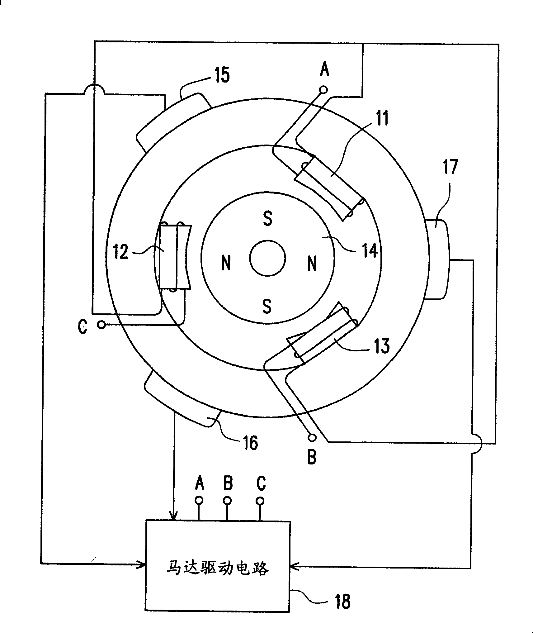
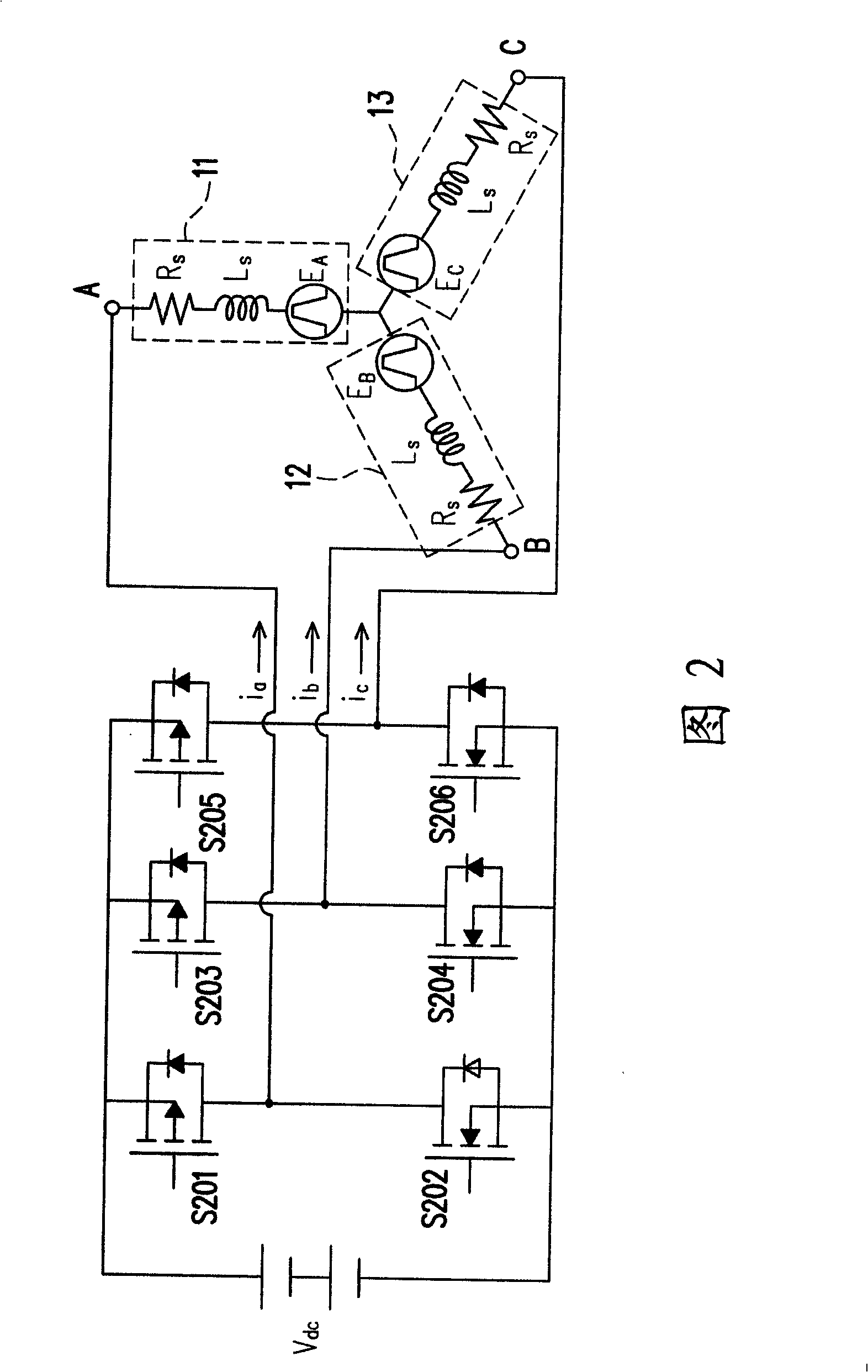
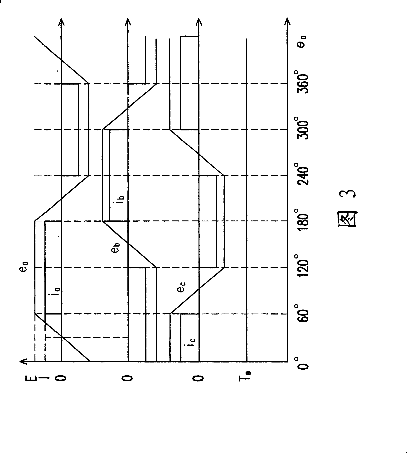
[0089] In order to solve the problems of the prior art, the present invention provides a rotor position detection method, a motor controller and a brushless motor. Before explaining the method and device, the back electromotive force closely related to the position of the motor is analyzed. The following will take the three-phase motor shown in Figure 2 as an example, and analyze it mathematically and electronically.

[0090] First, assume that the equivalent series resistance R of the stator coils 11-13 s is a fixed value, and it is assumed that the inductance L of the stator coils 11-13 s equal. Therefore, the voltage v at nodes A, B, and C of t...


PUM


Abstract

The invention relates to a motor control circuit and a brushless motor system, and provides a motor control method, circuit and brushless motor. The motor includes a three-phase coil, the first terminal of each coil is coupled at a node jointly. The method includes: when no current go through a first specific coil in the three-phase coil, and when the current flows from the second terminal of the second specific coil to the second terminal of the third specific coil, detecting the voltage at the second terminal of the first specific coil as a first appointment voltage; detecting the potential drop of the DC sensing resistor as a second appointment voltage; estimating the zero-cross point by the first appointment voltage, the second appointment voltage and the DC voltage supplied to the motor so as to control the motor. The invention is capable of detecting the zero-cross point of the motor in the PWM-off state, which further controls the phase change of motor, in addition, the invention can detect the zero-cross point by conjunction with PWM-off, thereby decreasing the phase change error, which is very practical.

Description

technical field [0001] The invention relates to a motor control technology, in particular to a motor control method, a motor control circuit and a brushless motor system. Background technique [0002] Adjustable speed motors are widely used in factory automation systems, ventilation systems, air conditioning systems, etc. The known adjustable speed motor is a motor in the form of a brush, and a brush-commutator is arranged on this motor. For the past century, commutation in brushed motors has been accomplished by graphite brushes touching an annular commutator mounted on the runner. However, the above-mentioned brushed motor is relatively bulky, generates a lot of noise during operation, and has low efficiency. With the advancement of technology, some people have developed a brushless motor (Brushless-Motor), and benefited from the advancement of design and material technology, its price has dropped sharply. Today, the cost difference between the two motor technologies is...

Claims


Application Information

Patent Timeline
Patent Type & Authority Applications(China)
IPC IPC(8): H02P6/18H02P6/08H02P6/182
Inventor 郑光耀
Owner PROLIFIC TECH INC
Learn More