
Method and device for detecting back EMF zero-crossing point of brushless DC motor

A brushed DC motor, zero-crossing detection technology, applied in electronic commutation motor control, electrical components, control systems, etc., can solve the problem that the number of back-EMF zero-crossing detections is reduced, the detection accuracy is reduced, and the control performance of brushless DC motors is affected. and other problems, to achieve the effect of increasing the number of sampling, improving detection accuracy and low cost

Active Publication Date: 2022-05-06
GUANGDONG MIDEA WHITE HOME APPLIANCE TECH INNOVATION CENT CO LTD +1
View PDF5 Cites 0 Cited by
  • Summary
  • Abstract
  • Description
  • Claims
  • Application Information

AI Technical Summary

Problems solved by technology

The detection accuracy of the back EMF zero point directly determines the accuracy of the commutation of the brushless DC motor, thus affecting the control performance of the brushless DC motor
Especially in the high-speed brushless DC motor control system, the number of PWM waves in each commutation cycle is very small, resulting in fewer counter-EMF zero-crossing detection times and lower detection accuracy.

Method used


Image

  • Method and device for detecting back EMF zero-crossing point of brushless DC motor
  • Method and device for detecting back EMF zero-crossing point of brushless DC motor
  • Method and device for detecting back EMF zero-crossing point of brushless DC motor

Examples


Embodiment Construction

[0040] Embodiments of the present invention are described in detail below, examples of which are shown in the drawings, wherein the same or similar reference numerals designate the same or similar elements or elements having the same or similar functions throughout. The embodiments described below by referring to the figures are exemplary and are intended to explain the present invention and should not be construed as limiting the present invention.

[0041] The method and device for detecting the back EMF zero-crossing point of the brushless DC motor, the control system of the brushless DC motor and the non-transitory computer-readable storage medium of the embodiments of the present invention will be described below with reference to the accompanying drawings.

[0042] First, refer to the attached Figure 4 Briefly describe the brushless DC motor control system of the embodiment of the present invention. Specifically, such as Figure 4 As shown, the control system includes...


PUM


Abstract

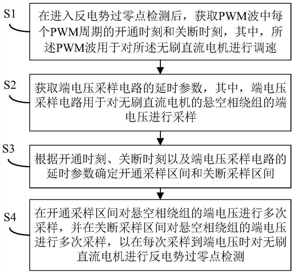
The present invention proposes a back EMF zero-crossing point detection method and detection device for a brushless DC motor, wherein the method includes: after entering the back-emf zero-crossing point detection, obtaining the turn-on moment and turn-off moment of each PWM cycle in the PWM wave, Obtain the delay parameters of the terminal voltage sampling circuit, and determine the on-sampling interval and the off-sampling interval according to the turn-on time, turn-off time and the delay parameters of the terminal voltage sampling circuit; in the turn-on sampling interval, the terminal voltage of the floating phase winding is measured several times Sampling, and sampling the terminal voltage of the suspended phase winding multiple times in the off-sampling interval, so as to detect the zero-crossing point of the back EMF of the brushless DC motor when the terminal voltage is sampled each time. The back EMF zero-crossing point detection method of the embodiment of the present invention can accurately detect the back-emf zero-crossing point of the brushless DC motor when the motor speed is very high and the number of PWM waves is small, reducing the commutation error at high speed, And the cost is low.

Description

technical field [0001] The invention relates to the technical field of motor control, in particular to a detection method and a detection device for a counter electromotive force zero-crossing point of a brushless DC motor. Background technique [0002] Brushless DC motors are widely used because of their small size, high efficiency, and simple control. In order to reduce the hardware cost of the control system, a control scheme without a position sensor is mostly used, that is, the commutation is realized by detecting the zero-crossing point of the back EMF. The detection accuracy of the back EMF zero point directly determines the commutation accuracy of the brushless DC motor, thus affecting the control performance of the brushless DC motor. Especially in the high-speed brushless DC motor control system, the number of PWM waves in each commutation cycle is very small, resulting in fewer counter-EMF zero-crossing detection times and lower detection accuracy. Contents of ...

Claims


Application Information

Patent Timeline
Patent Type & Authority Patents(China)
IPC IPC(8): H02P6/182
CPCH02P6/182
Inventor 彭壮张筑亚宾宏
Owner GUANGDONG MIDEA WHITE HOME APPLIANCE TECH INNOVATION CENT CO LTD
Learn More