A pivot hinge and a pivot window

A hinge and pivoting technology, applied in the field of pivoting hinges, can solve problems such as ignoring hinge position changes

Inactive Publication Date: 2008-09-03
VKR HLDG AS
View PDF6 Cites 8 Cited by
  • Summary
  • Abstract
  • Description
  • Claims
  • Application Information

AI Technical Summary

Problems solved by technology

Therefore, the resources spent on developing new hinges are focused on optimizing the interaction between the h

Method used


Image

  • A pivot hinge and a pivot window
  • A pivot hinge and a pivot window
  • A pivot hinge and a pivot window

Examples


Embodiment Construction

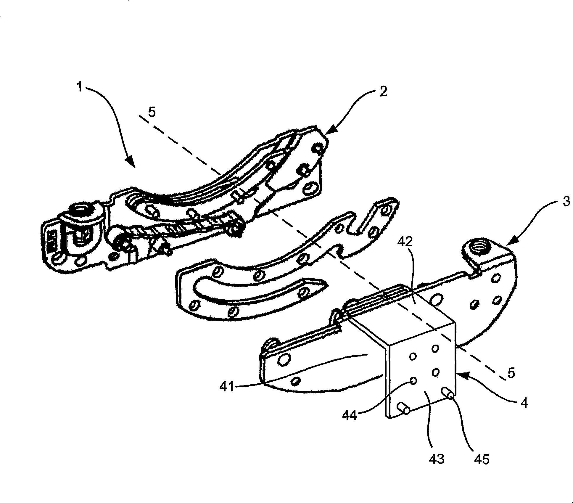
[0022] figure 1 The hinge 1 in includes three main parts, namely a first hinge part 2, a second hinge part 3 and a connecting piece 4, wherein, in the embodiment shown, the connecting piece 4 is fixed to the sash hinge part by rivets.

[0023] The second hinge part 3 is pivotable about a hinge axis 5 relative to the first hinge part 2 . Since the hinge shown is a pivot hinge for a roof window, the hinge axis is located outside the hinge part, ie slightly above the hinge part. The position of the hinge axis ensures that pivotal movement is possible without parts of the first and second members of the structure colliding with each other. This aspect will be described in more detail below.

[0024] The connecting piece 4 and the second hinge part form an inverted U-shaped unit comprising: in the embodiment shown, a first foot 41 formed by the second hinge part 3; a middle part 42 of the surface of one of the members to be connected by the hinge; and a second leg 43 for connect...


PUM


Abstract

The invention relates to a pivot hinge (1) with a first part (2) intended to be secured to a substantially stationary first member (20) and a second part (3) intended to be secured to a second member (30), the second hinge part being pivotable in relation to the first hinge part about a hinge axis (5). A connecting piece (4) is provided, where a first end (41) of the connecting piece is attached to the second hinge part and a second end (43) comprises means (44,45) for securing the connecting piece to the second member. The second end is arranged at a distance from the second hinge part seen in parallel with the hinge axis. The hinge may be used in a pivot window (10) with a sash (30) and a frame (20), where the sash may be turned in relation to the frame about the hinge axis (5). The hinge is secured to the surface of the frame member facing away from the sash member or in a recess (7) formed in an upper surface of the frame side member and the sash hinge part is connected to the sash side member via the connecting piece (4) spanning at least a part (25) of the frame member.

Description

technical field [0001] The present invention relates to a pivot hinge comprising a first part for fixing to a first substantially stationary member and a second part for fixing to a second member, the second hinge part being pivotable relative to the first hinge part A hinge axis located outside the hinge part pivots. The invention also relates to a window comprising a hinge as described above. Background technique [0002] Hinges of this type are known from numerous publications, such as the applicant's published International Patent Application No. WO9928581 and British Patent No. GB1028251. The hinges disclosed in these documents are suitable for mounting on windows, wherein the frame member corresponds to the first member and the sash member corresponds to the second member. These hinges consist of two hinge parts which are respectively directly attached to the surface of the first and second member so that the two hinge parts face each other. The hinge is arranged be...

Claims


Application Information

Patent Timeline
IPC IPC(8): E05D1/04E05D5/06
CPCE05D5/06E05Y2900/148E05D1/04E04D13/0354
Inventor 艾伦·埃德瓦德森
Owner VKR HLDG AS
Why Eureka
Try Eureka