
Direct driving type mainshaft head and synthetic processor and manufacturing method thereof

A spindle head, direct-drive technology, applied in the direction of metal processing machinery parts, manufacturing tools, metal processing equipment, etc., can solve the problems of weak structural rigidity, difficult control of processing accuracy, and ineffective adjustment of assembly

Inactive Publication Date: 2008-09-10
乔福机械股份有限公司
View PDF2 Cites 4 Cited by
  • Summary
  • Abstract
  • Description
  • Claims
  • Application Information

AI Technical Summary

Problems solved by technology

The motor stators of the two axial rotation mechanisms of US5,584,621 are all outside the motor rotor. When the A-axis rotation mechanism is assembled, the components must be placed and installed sequentially from the outside to the inside of the yoke, because the yoke is integrally formed by casting It is not easy to control the manufacturing and machining accuracy, and it cannot be adjusted effectively during assembly, so the problem of oil leakage is prone to occur during operation
The prior art US6,669,416 discloses another direct-drive spindle head, the motor rotors of the two axial rotation mechanisms are all outside the motor stator, but the axial angle between the two rotation mechanisms is 45 degrees, and the machining accuracy Difficult to control and weak structural rigidity

Method used


Image

  • Direct driving type mainshaft head and synthetic processor and manufacturing method thereof
  • Direct driving type mainshaft head and synthetic processor and manufacturing method thereof
  • Direct driving type mainshaft head and synthetic processor and manufacturing method thereof

Examples


Embodiment Construction

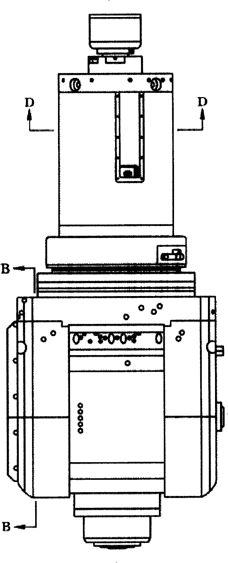
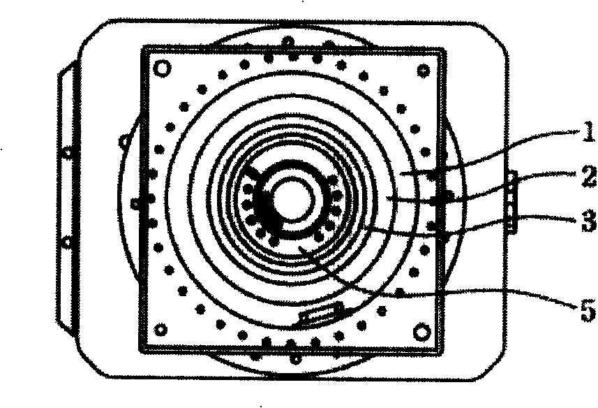
[0045] Since the present invention discloses a direct-drive spindle head assembly (Spindle Assembly) of a comprehensive processing machine, the basic principle and basic structure of the comprehensive processing machine used therein have been understood by those skilled in the art, so the following Description, no complete description. At the same time, the accompanying drawings that are compared below are schematic structural representations related to the features of the present invention, and are not and need not be completely drawn according to actual dimensions, so please describe first.

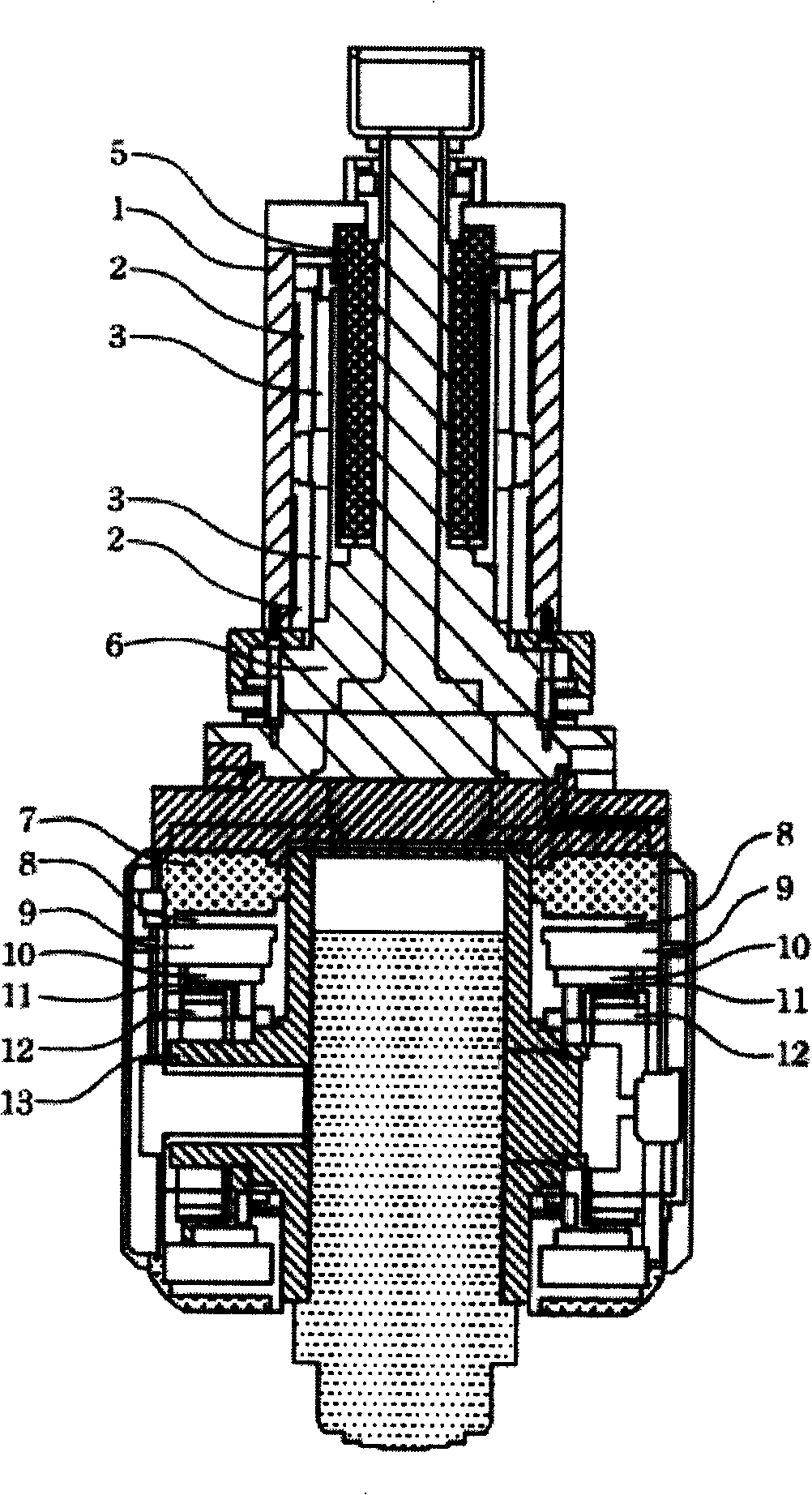
[0046] First please refer to figure 1 , which is the first preferred embodiment provided by the present invention, is a direct drive spindle assembly (Direct drive spindle assembly), which is mainly composed of a main fork, a first drive means, a second It consists of a second drive means and a spindle box 13 (Spindle box). Wherein, the main fork has a base 6 and a pair of fork arms 7...


PUM


Abstract

The invention discloses a direct drive spindle assembly which comprises a main fork that is provided with a base and a pair of paralleling separated fork arms and can rotate around an axis of a first rotation axis; a first drive means is provided with a hollow shell body, a first motor stator and a first motor rotator; wherein, the first rotator is coupled with the base of the main fork, thus driving the main fork to rotate around the first rotation axis; a second drive means is contained between the fork arms of the main fork and is provided with a pair of a second motor stator, a second motor rotator and a rotator transmission ring that are concentric with a second rotation axis, the second rotation axis is positively crossed with the first rotation axis, and the second motor stator is coupled with the fork arms of the main fork. The invention is also provided with a main spindle box to be an orthogonal cross structure, a first arm of the orthogonal cross structure is coupled with the second motor rotator by the rotator transmission ring, and a second arm of the orthogonal cross structure is connected with a spindle head. The direct drive spindle assembly is characterized in that the pair of fork arms is assembled to the base of the main fork after the second drive means is arranged and is positioned and locked, thus achieving better adjusting precision.

Description

technical field [0001] The present invention relates to a comprehensive processing machine and a manufacturing method thereof, in particular to a comprehensive processing machine whose main shaft head has a direct drive (Direct Drive) transmission component. Background technique [0002] In the multi-axis rotating comprehensive processing machine used in the known technology, the rotation of the spindle head is mostly driven by the spindle motor at the far end through transmission components such as timing belt sets, rack and pinion sets, worm gear sets, bevel gear sets, and spur gears. Driven by a group or a combination of the above components. In order to adapt to various complex surface structure requirements of molds or aerospace parts, the spindle head (spindle head) must maintain a specific angle with the surface structure of the workpiece when it is running at high speed to process the surface structure of the workpiece, and on the surface of the workpiece When the c...

Claims


Application Information

Patent Timeline
IPC IPC(8): B23Q1/54B23Q5/20B23Q5/10B23Q11/12H02K7/102H02K7/14
Inventor 曹向远林俊杰
Owner 乔福机械股份有限公司
Learn More