
Beating machine

A technology of driving machine and contact arm, which is applied in the direction of portable motorized devices, nailing tools, manufacturing tools, etc., and can solve problems such as operational damage of driving machines

Inactive Publication Date: 2010-04-21
MAKITA CORP
View PDF7 Cites 0 Cited by
  • Summary
  • Abstract
  • Description
  • Claims
  • Application Information

AI Technical Summary

Problems solved by technology

The external force acts (reacts) in the direction of lifting the driver body from the driving material, so the user needs to push the driver body in the driving direction with a correspondingly large force. , the operability of the driver is impaired

Method used


Image

  • Beating machine
  • Beating machine
  • Beating machine

Examples


Embodiment Construction

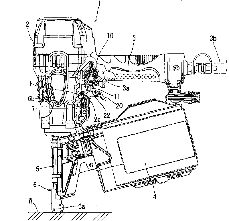
[0028] Below, based on Figure 1 to Figure 7 Embodiments of the present invention will be described. figure 1 The driver 1 according to this embodiment is shown. In this embodiment, as the driver 1 , a compressed air nail driver that operates using compressed air as a driving source is exemplified. The same can also be provided for screwdrivers. In addition, in this specification, the direction in which the driver is driven is set as the lower side, and it is used for description of each structure and member.

[0029] This driver 1 includes a main body 2 , a handle 3 and a staple magazine 4 . A piston and an air cylinder for driving a driver (nail) into a driving material are incorporated in the main body 2 . A firing pin for driving the driving part is installed on the piston. The striker moves within a striker guide rail 5 protruding from the lower surface of the main body 2 . Drivers are supplied one by one into the striker guide rail 5 .

[0030] Intake and exhaust of...


PUM


Abstract

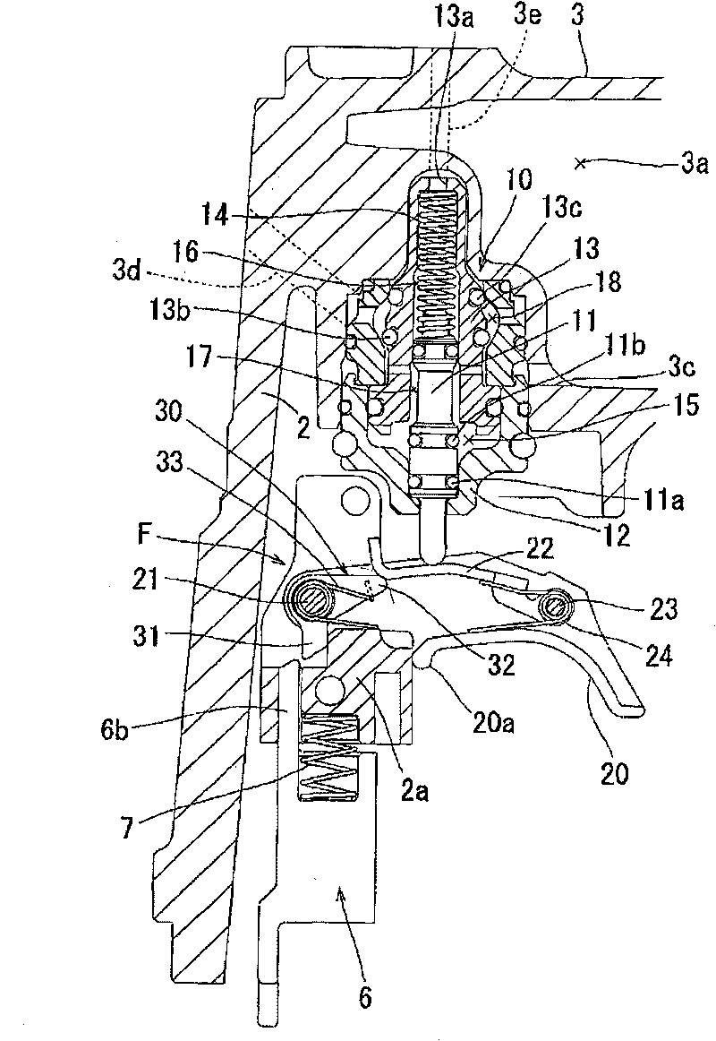
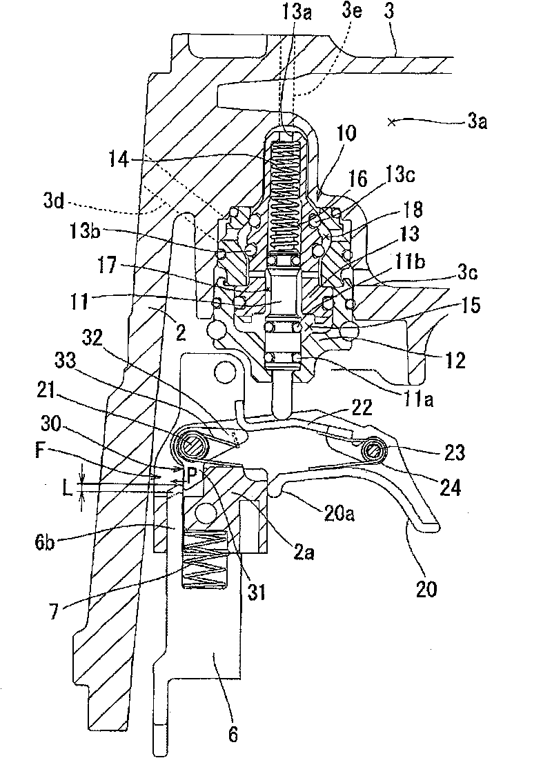
The invention provides a driven machine. When a down pressing operation is processed to the driven machine mainbody, a contact arm for preventing error action is moved to an opening position, and a handle level processes an latch pulling operation, a triggered valve opens and processes driven action. In the driven machine, an acting force of the triggered valve to close position acts on the contact arm, so down pressure of the mainbody becomes large relatively and operation becomes poor. The driven machine provided by the invention can eliminate the problem. An acting force (14) of a valve rod(11) acts on an action arm (6b) of the contact arm (6) along direction orthogonal with movable direction, and does not become resistance in movable direction, and reduces down pressure.

Description

technical field [0001] The present invention relates to, for example, a nail driver or a screw driver, which operates by using compressed air as a driving source. Background technique [0002] For example, a gas-driven nailing machine has a main body part in which a piston and an air cylinder reciprocating by compressed air are built in, and a handle part is provided in a state protruding sideways from the main body part. A driver guide is provided as a firing port for driving nails. In addition, generally, at the base of the handle portion, there are provided a switch lever in the form of a trigger operated by the user with a fingertip, and a trigger valve (trigger valve) that operates thereby to open and close the air cylinder on the main body portion side. When the user pulls the switch lever with his fingertips, the trigger valve opens to supply compressed air to the cylinder of the main body, thereby moving the piston down and striking a nail supplied to the striker gu...

Claims


Application Information

Patent Timeline
Patent Type & Authority Patents(China)
IPC IPC(8): B25C1/00B25F5/00
Inventor 石川直治
Owner MAKITA CORP
Learn More