Light choppers

A technology of optical chopper and rotating shaft, which is applied in the direction of optics, instruments, optical components, etc., and can solve the convenience and disadvantages of simplifying equipment measurement

Active Publication Date: 2008-09-10
SHENZHEN KECHUANG DIGITAL DISPLAY TECH
View PDF0 Cites 4 Cited by
  • Summary
  • Abstract
  • Description
  • Claims
  • Application Information

AI Technical Summary

Problems solved by technology

[0004] However, the optical chopper used in the existing mechanical modulation method can only modulate the reference light, and the measurement optica

Method used


Image

  • Light choppers
  • Light choppers
  • Light choppers

Examples


Embodiment Construction

[0022] In order to further elaborate the technical means and effects adopted by the present invention to achieve the predetermined purpose, please refer to the following detailed description and accompanying drawings of the present invention. It is believed that the purpose, characteristics and characteristics of the present invention should be able to gain a deep and specific understanding from this , however, the accompanying drawings are provided for reference and illustration only, and are not intended to limit the present invention.

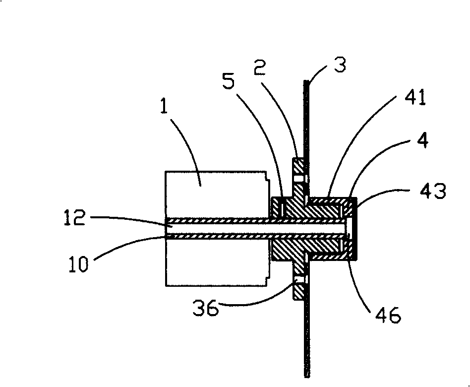
[0023] refer to figure 1 , The optical chopper of the present invention includes: a stepping motor 1, a flange 2 fixedly sleeved on the motor shaft 10, a modulation disc 3 fixedly installed on the flange 2, and a polarizer 4 installed on the flange 2. The rotating shaft 10 is provided with an axial through hole 12, that is, it is a hollow shaft.

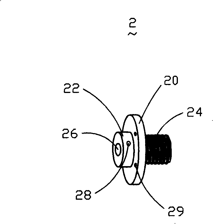
[0024] Please also see figure 2 The flange 2 includes a flange plate 20, a fixed portion 22 ...


PUM


Abstract

The invention relates to an optical chopper, which comprises a motor, a modulation reticle arranged on a rotating shaft of the motor and a polarizer arranged at the terminal of the rotating shaft of the motor; the rotating shaft is provided with an axial through hole. The optical chopper has the advantages that, the modulation reticle and the polarizer fixed on the rotating shaft of the motor respectively and simultaneously performs mechanical modulation to reference light and measurement light, therefore, measuring equipment is greatly simplified, and measuring accuracy and convenience are improved.

Description

technical field [0001] The invention relates to an optical chopper, in particular to an optical chopper with a modulation disc and a polarizer. Background technique [0002] The thickness of the liquid crystal layer of a liquid crystal display plays an important role in image quality. Therefore, the thickness of the liquid crystal layer is listed as one of the important monitoring parameters in the manufacturing process of the liquid crystal display. [0003] At present, there are many light modulation methods used to measure the thickness of the liquid crystal layer, including acousto-optic, electro-optic, magneto-optical modulation, and mechanical modulation. Among them, although the frequency adjustment range of the mechanical modulation method is not large, it is suitable for low-frequency modulation and has low cost, so it has been widely used. [0004] However, the optical chopper used in the existing mechanical modulation method can only modulate the reference light,...

Claims


Application Information

Patent Timeline
IPC IPC(8): G02B26/04G02F1/00
Inventor 刘守裕李方红常嘉兴周立马红虎刘军
Owner SHENZHEN KECHUANG DIGITAL DISPLAY TECH
Why Eureka
Try Eureka