Vertical vibration layer energy converter round disk stator and ultrasonic electromotor using this stator

A technology of ultrasonic motors and transducers, applied in the direction of piezoelectric effect/electrostrictive or magnetostrictive motors, generators/motors, electrical components, etc., can solve problems such as mechanical output capacity constraints, and achieve electromechanical coupling efficiency High, improve the output torque of the motor and prolong the service life

Inactive Publication Date: 2008-09-10
HARBIN INST OF TECH
View PDF0 Cites 10 Cited by
  • Summary
  • Abstract
  • Description
  • Claims
  • Application Information

AI Technical Summary

Problems solved by technology

[0003] In order to solve the problem that the mechanical output capability of the existing ultrasonic motor is restricted by the method of pasting the piezoelectric ceramic sheet with metal elastic body, the present invention Provided is a longitudinal vibration sandwich transducer type disc stator and an ultrasonic motor using the stator

Method used


Image

  • Vertical vibration layer energy converter round disk stator and ultrasonic electromotor using this stator
  • Vertical vibration layer energy converter round disk stator and ultrasonic electromotor using this stator
  • Vertical vibration layer energy converter round disk stator and ultrasonic electromotor using this stator

Examples


specific Embodiment approach 1

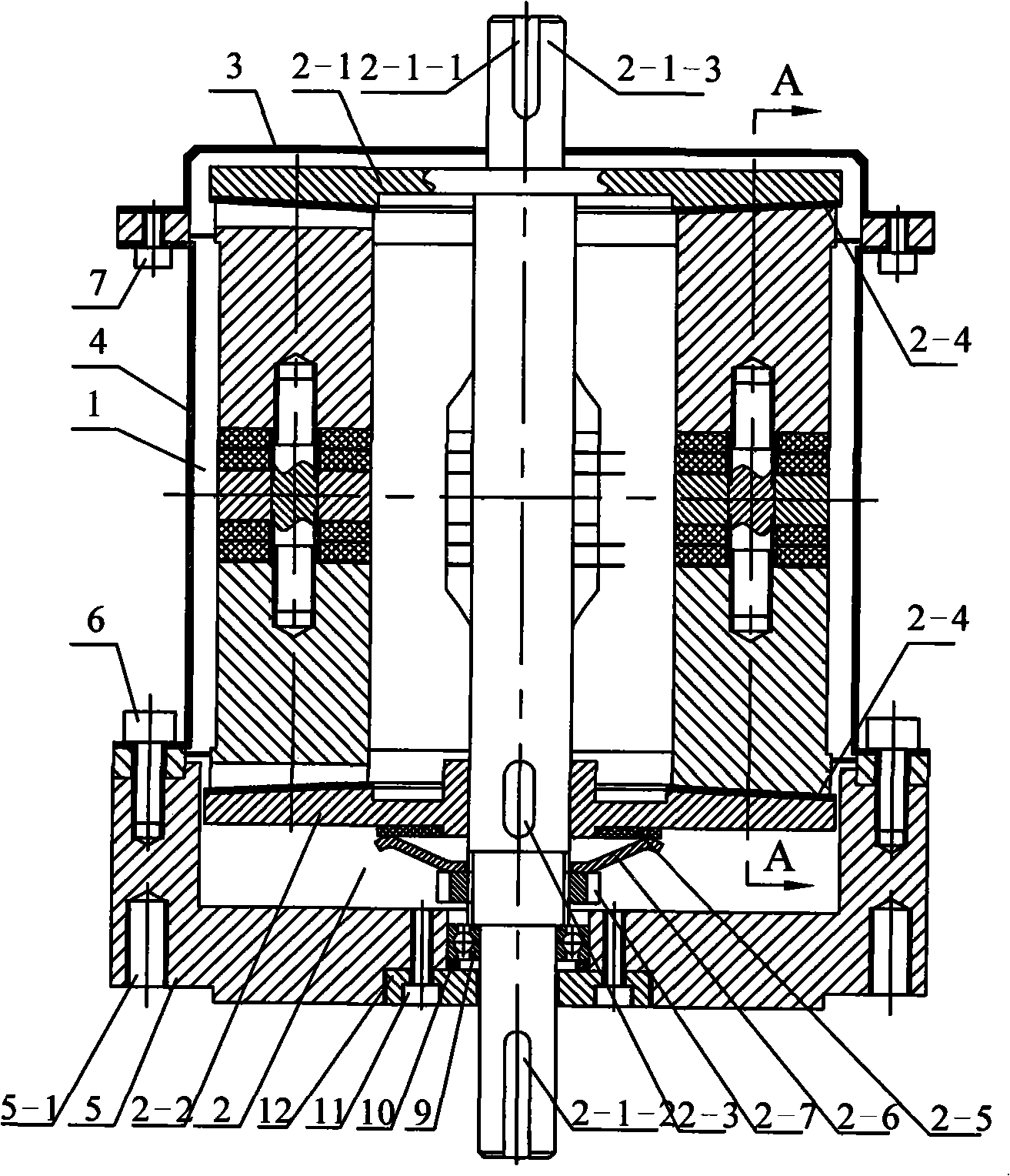
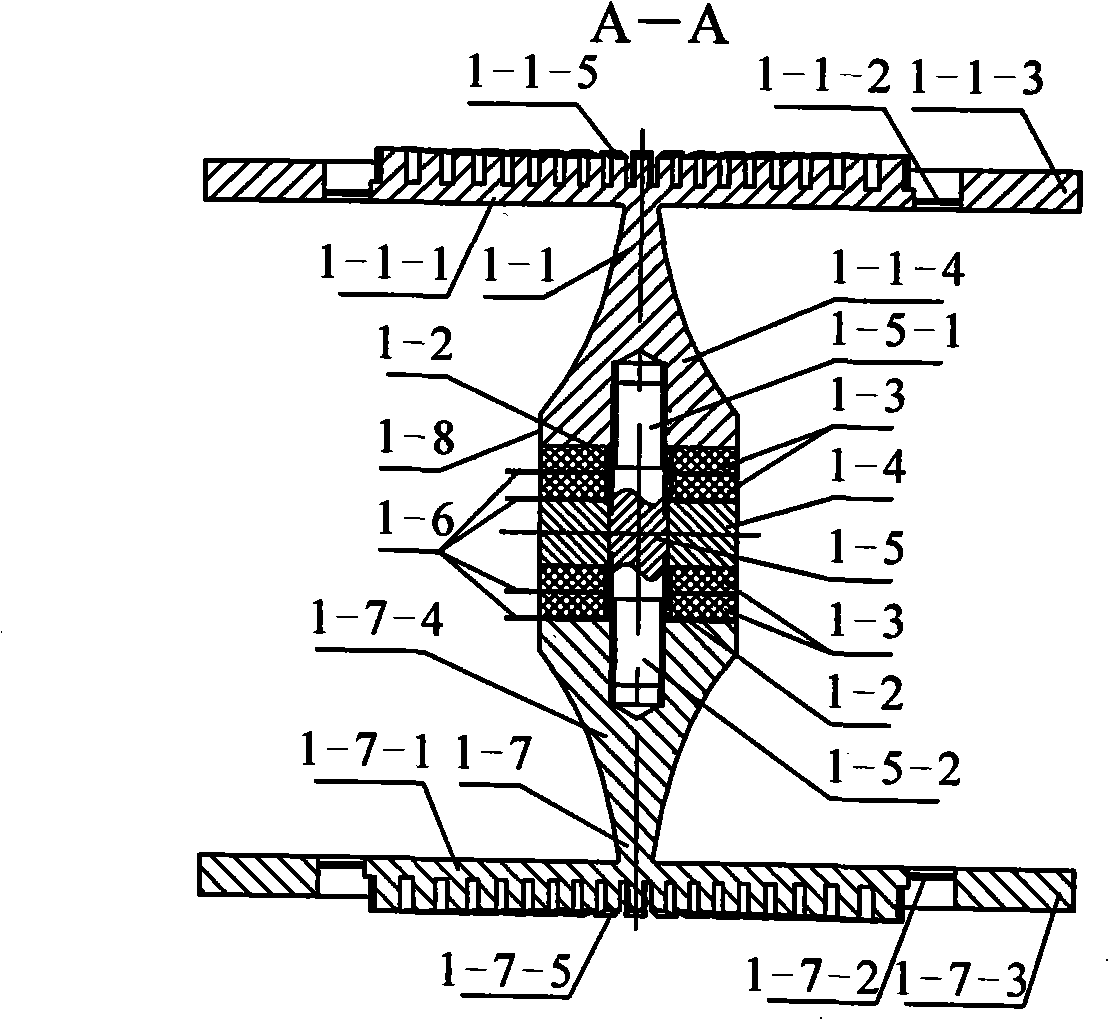
[0010] Specific Embodiment 1: In this embodiment, the longitudinal vibration sandwich transducer type disc stator is composed of an upper end disc 1-1-1, a lower end disc 1-7-1 and an even number of longitudinal vibration sandwich transducers 1-8 ; The even number of longitudinal vibration sandwich transducers 1-8 are symmetrically fixed between the upper disc 1-1-1 and the lower disc 1-7-1, and each longitudinal vibration sandwich transducer 1-8 is formed by a front end Cover 1-1-4, rear end cover 1-7-4, insulating sleeve 1-2, two pairs of piezoelectric ceramic sheets 1-3, flange 1-4, pretension shaft 1-5 and thin copper electrode 1 -6 composition; the front end cover 1-1-4 and the rear end cover 1-7-4 are quadrangular prisms whose cross section is rectangular and tapered, the small end face of the front end cover 1-1-4 and the upper disc 1-1 -1 is fixedly connected to the lower end surface, and the small end surface of the rear end cover 1-7-4 is fixedly connected to the upp...

specific Embodiment approach 2

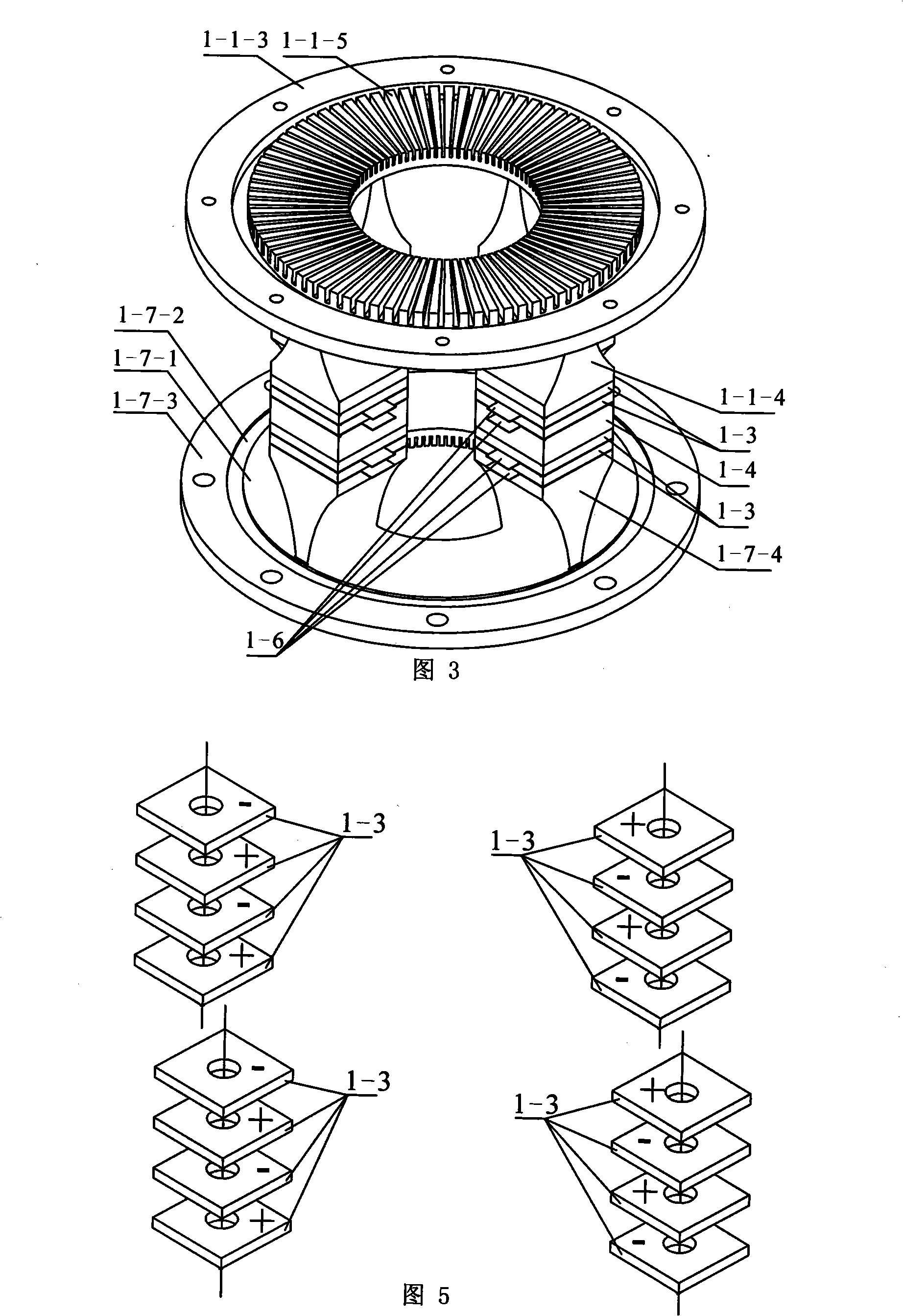
[0013] Specific implementation mode two: combination figure 2 , Fig. 3 illustrates this embodiment, the difference between this embodiment and the specific embodiment is that the front end cover 1-1-4 and the upper end disc 1-1-1, the rear end cover 1-7-4 and the lower end disc 1-7-1 respectively use a whole piece of metal material to process the end cap / disc as one piece. Other compositions and connection methods are the same as those in Embodiment 1. This processing method can achieve the purpose of reducing energy loss, and is conducive to improving the controllability of the particle vibration track on the surface of the driving tooth.

specific Embodiment approach 3

[0014] Specific Embodiment 3: This embodiment is described in conjunction with FIG. 3. The difference between this embodiment and Embodiment 1 is that the upper end surface of the upper end disc 1-1-1 and the lower end surface of the lower end disc 1-7-1 are respectively Continuous comb-shaped driving teeth are processed, and the upper end cone surface 1-1-5 is processed on the continuous comb-shaped driving teeth on the upper end surface of the upper end disc 1-1-1, and the outer sides of the upper end disc 1-1-1 are respectively processed There are thin-walled rings 1-1-2 on the upper end and flanges 1-1-3 on the upper end; the lower conical surface 1-7-5 is processed on the continuous comb-shaped driving teeth on the lower end of the lower disc 1-7-1. The outer side of the lower disc 1-7-1 is respectively processed with a lower end face thin-walled ring 1-7-2 and a lower end face flange 1-7-3. Other compositions and connection methods are the same as those in Embodiment 1. ...


PUM


Abstract

The invention discloses a longitudinal vibration sandwiched energy converter-typed round disc stator and an ultrasonic motor to which the stator is applied, and relates to the ultrasonic motor field. The invention solves the problem in the existing ultrasonic motor that mechanical output capacity is restrained due to the adoption of elastic metal body stuck on piezoelectric ceramic pieces for excitation. Even longitudinal vibration sandwiched energy converters of the stator are symmetrically arrayed and fixed between a round disc at the upper end and a round disc at the lower end; both the front end cover and the back end cover of the sandwiched energy converter are a quadrangular with a rectangle cross section and narrowing down gradually, the small end faces of the front end cover and the back end cover are fixedly connected with the upper round disc and the lower round disc; a flange is arranged at the section where the energy converter vibrates longitudinally and two pairs of piezoelectric ceramic pieces are respectively fixed between the front end cover and the back end cover and the flange. A rotor with a shaft and a rotor without a shaft in the ultrasonic motor both take the shape of a round disc and are embedded respectively from the top and the bottom of a stator cylinder, a wearable cushion is fixed at the end face, contacting the round disc, of the rotor and the stator is fixed to a base through the flange on the energy converter. The longitudinal vibration sandwiched energy converter-typed round disc stator and the ultrasonic motor of the invention are applicable to the manufacturing field of the ultrasonic motor.

Description

technical field [0001] The invention relates to a longitudinal vibration sandwich transducer type disk stator and an ultrasonic motor using the stator, belonging to the technical field of piezoelectric ultrasonic motors. Background technique [0002] Piezoelectric ultrasonic motor is a kind of piezoelectric ultrasonic motor that uses the inverse piezoelectric effect of piezoelectric ceramics to excite vibration in the ultrasonic frequency range in the elastic body, and forms a particle motion with a specific trajectory at a specific point or area on the surface of the elastic body, and then passes through the stator, The frictional coupling between the rotors converts the microscopic motion of the particle into the macroscopic motion of the rotor. It has the advantages of low speed and high torque, no need for a transmission mechanism, no electromagnetic interference, fast response, and self-locking when power is off. As a piezoelectric driver, it has Very wide range of appl...

Claims


Application Information

Patent Timeline
Patent Type & Authority Applications(China)
IPC IPC(8): H02N2/12H02N2/10
Inventor 刘军考刘英想陈维山谢涛石胜君
Owner HARBIN INST OF TECH
Why Eureka
Try Eureka