
Magnetically levitated transport system

A technology of magnetic levitation and transportation device, applied in the direction of propulsion system, transportation and packaging, magnetic circuit, etc., can solve the problem of no linear electromagnetic machine and so on

Inactive Publication Date: 2008-09-10
杜米特鲁·博吉科
View PDF8 Cites 11 Cited by
  • Summary
  • Abstract
  • Description
  • Claims
  • Application Information

AI Technical Summary

Problems solved by technology

However, the prior art does not suggest a linear electromagnetic machine that provides an electromagnetic field immersed in the field of a unipolar permanent magnet of opposite polarity, like the device of the present invention; and operates in an electromagnetic induction manner

Method used


Image

  • Magnetically levitated transport system
  • Magnetically levitated transport system
  • Magnetically levitated transport system

Examples


Embodiment Construction

[0024]The above-referenced drawings illustrate at least one preferred, best mode embodiment of the apparatus and method of use thereof described in the following detailed description. Changes and modifications to what is described herein can be made by those skilled in the art without departing from the spirit and scope of the invention. Therefore, it must be understood that those given are only examples and they should not be taken as limiting the scope of the apparatus and method of the present invention.

[0025] figure 1 ~5 illustrates the device described here, which operates on the principles representing a principal application as an extension of the device defined in U.S. Patent Application No. 11200920, filed August 9, 2005, with the same common theoretical basis.

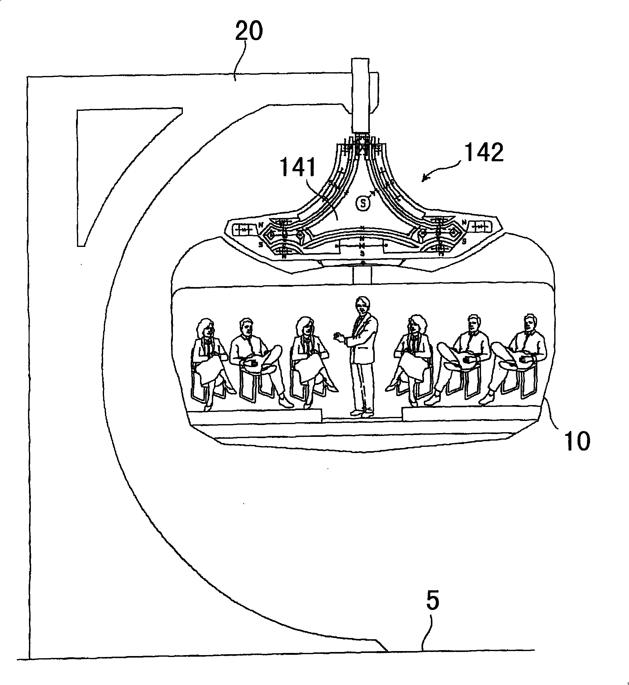
[0026] figure 1 is a cross-sectional view of a magnetic levitation transportation system illustrating a suspended vehicle 10 of the present invention fixedly mounted on a translator 142 for loading pass...


PUM


Abstract

The present invention is a magnetically levitated transport system showing a suspended vehicle for carrying passengers and freight fixedly mounted to a translating portion of the linear motor system of the present invention which has the functions of providing levitated positioning of the vehicle as well as propulsion and braking. The translating portion is movably engaged with a long linear ferromagnetic core which is fixed to railway supports mounted above a ground surface. Other ways of supporting and suspending the vehicle are clearly possible as well. Electromagnets are located at opposing sides of a fixed linear ferromagnetic core of a DC linear electric motor-generator. These electromagnets, in a typical application are interconnected initially in parallel electrical interconnection and are later switched to series electrical interconnection as vill be described below. Certain benefits may be obtained by this ability to switch between parallel and series interconnection.

Description

[0001] related application [0002] This application claims international priority to US Patent Application No. 11209916, filed August 22, 2005, entitled "Magnetically Levitated Transport System." technical field [0003] Generally, the present invention relates to electric motor-generators. In particular, the present invention relates to DC linear electromagnetic machines operating by electrical induction. Background technique [0004] The following illustrates the current state of the art in respect of the device described and claimed herein. [0005] US 2004 / 0135452 by Tu et al. discloses a planar rotating generator comprising at least one toroidal coil structure for cutting magnetic field lines to induce current and at least one disc-shaped magnetic pole structure parallel to the helical coil. If a plurality of toroidal coil structures and disc-shaped magnetic coil structures are included, the toroidal coil structures and disc-shaped magnetic coil structures are arrang...

Claims


Application Information

Patent Timeline
Patent Type & Authority Applications(China)
IPC IPC(8): H02K41/00H02K7/09
CPCH02N15/00H02K2201/03H02K41/031H02K7/09B60L13/04
Inventor 杜米特鲁·博吉科
Owner 杜米特鲁·博吉科
Learn More