Cast-in-place concrete tower with prefabricated spatial steel bar truss formwork and construction method of cast-in-place concrete tower

A steel truss and concrete technology, which is applied in the field of cast-in-place concrete wind power tower construction, can solve the problems of large hoisting tonnage, time-consuming and laborious construction process, etc., and achieve the effect of reducing construction costs, saving construction costs, and reducing procedures

Active Publication Date: 2016-11-09
CHINA AVIATION PLANNING & DESIGN INST GRP
View PDF7 Cites 14 Cited by
  • Summary
  • Abstract
  • Description
  • Claims
  • Application Information

AI Technical Summary

Problems solved by technology

[0003] The purpose of the present invention is to provide a prefabricated space steel truss formwork cast-in-place concrete tower and its construction method, to solve the technical problem of excessive hoisting tonnage in the construction process of the prior art; Carry out template removal process, resulting in time-consuming and labor-intensive problems in the construction process

Method used


Image

  • Cast-in-place concrete tower with prefabricated spatial steel bar truss formwork and construction method of cast-in-place concrete tower
  • Cast-in-place concrete tower with prefabricated spatial steel bar truss formwork and construction method of cast-in-place concrete tower
  • Cast-in-place concrete tower with prefabricated spatial steel bar truss formwork and construction method of cast-in-place concrete tower

Examples


Embodiment Construction

[0031] In order to make the technical means, innovative features, objectives and effects achieved by the present invention easy to understand, the present invention will be further described with reference to the accompanying drawings.

[0032] The embodiments described herein are specific specific implementations of the present invention, which are used to illustrate the concept of the present invention. They are all explanatory and exemplary, and should not be construed as limiting the embodiments of the present invention and the scope of the present invention. In addition to the implementation exceptions described here, those skilled in the art can also adopt other obvious technical solutions based on the contents disclosed in the claims and specification of this application. These technical solutions include any obvious changes to the embodiments described herein. Technical solutions for replacement and modification.

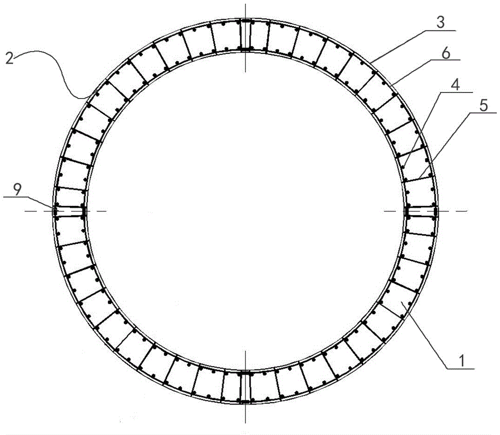
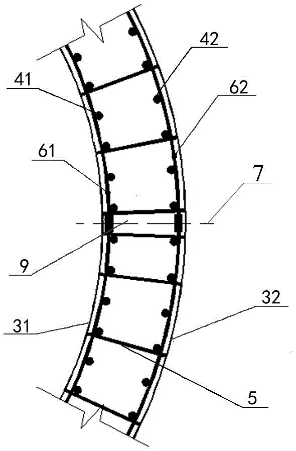
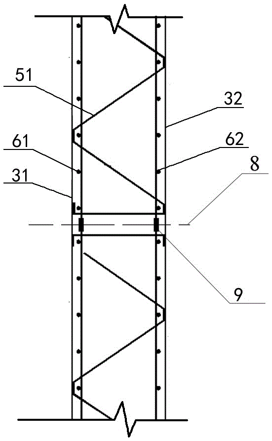
[0033] The invention provides a cast-in-place concrete towe...


PUM


Abstract

The invention discloses a cast-in-place concrete tower with a prefabricated spatial steel bar truss formwork and a construction method of the cast-in-place concrete tower. The cast-in-place concrete tower comprises the spatial steel bar truss formwork and concrete cast into the spatial steel bar truss formwork in place, and is characterized in that the spatial steel bar truss formwork is a disposable prefabricated formwork, is formed by splicing a plurality of spatial steel bar truss formwork units and is in a cylinder shape; each spatial steel bar truss formwork unit is of an arc-shaped sheet structure and comprises reinforcing bars in the middle and disposable steel formworks attached to the inner and outer sides of the reinforcing bars respectively, wherein the reinforcing bars comprise an inner layer of evenly-arranged vertical stressed steel bars, an outer layer of evenly-arranged vertical stressed steel bars, horizontal stressed steel bars used for tying the vertical stressed steel bars on the same layer, and tie stirrups arranged in a radial mode and used for tying the inner layer of vertical stressed steel bars, the outer layer of vertical stressed steel bars and the horizontal stressed steel bars at the same time. By adopting the technology, it is only needed to install the spatial steel bar truss formwork in a hoisting mode in site construction, the hoisting weight is greatly reduced, the needed crane tonnage is greatly reduced, and the construction cost is greatly reduced.

Description

Technical field [0001] The invention relates to the technical field of construction of cast-in-place concrete wind power generation towers, in particular to a cast-in-situ concrete tower of a prefabricated spatial steel bar truss template and a construction method thereof. Background technique [0002] The prefabricated segments of the precast concrete wind power tower are relatively large, and the weight of a single piece is generally 30 to 60 tons. The construction site requires a thousand-ton crane to hoist the prefabricated power tower section in place, resulting in extremely high lifting costs and uneconomical. If the cast-in-place concrete tower is used, it will face the problems of high-altitude formwork and high-altitude binding of steel bars. The construction period is very long and the construction is difficult, resulting in high construction costs. Summary of the invention [0003] The purpose of the present invention is to provide a cast-in-place concrete tower of pref...

Claims


Application Information

Patent Timeline
Patent Type & Authority Applications(China)
IPC IPC(8): E04H12/12E04G13/00E04G21/02
CPCE04G13/00E04G21/02E04H12/12
Inventor 张曼生葛家琪张国军王树
Owner CHINA AVIATION PLANNING & DESIGN INST GRP
Why Eureka
Try Eureka