Forming die for resin screw gear and resin screw gear using the forming die

A technology for forming molds and helical gears, applied in the direction of gears, elements with teeth, belts/chains/gears, etc., to achieve the effect of simple structure

Inactive Publication Date: 2008-09-17
RICOH KK
View PDF2 Cites 2 Cited by
  • Summary
  • Abstract
  • Description
  • Claims
  • Application Information

AI Technical Summary

Problems solved by technology

[0019] However, when such a disc gate is used to ensure the molding accuracy of the tooth portion 4, the same residual portion as the number of the set disc gate will be left on the end surface 2b of the rotating shaft portion 2, so there is a need to modify the resin. The problem of cutting the end surface 2b of the rotating shaft part 2 of the helical gear 1 for finishing

Method used


Image

  • Forming die for resin screw gear and resin screw gear using the forming die
  • Forming die for resin screw gear and resin screw gear using the forming die
  • Forming die for resin screw gear and resin screw gear using the forming die

Examples


Embodiment 1

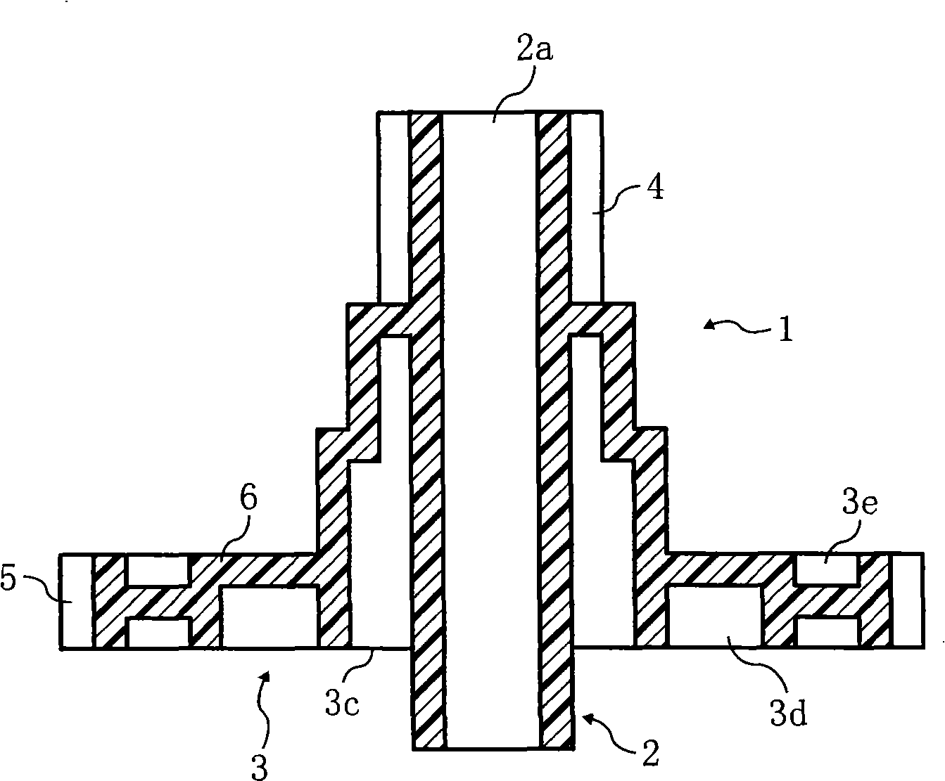
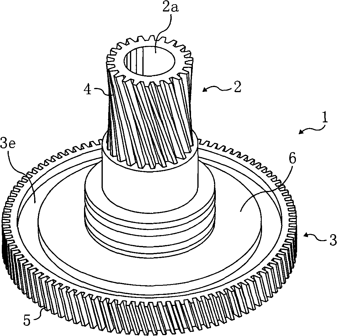
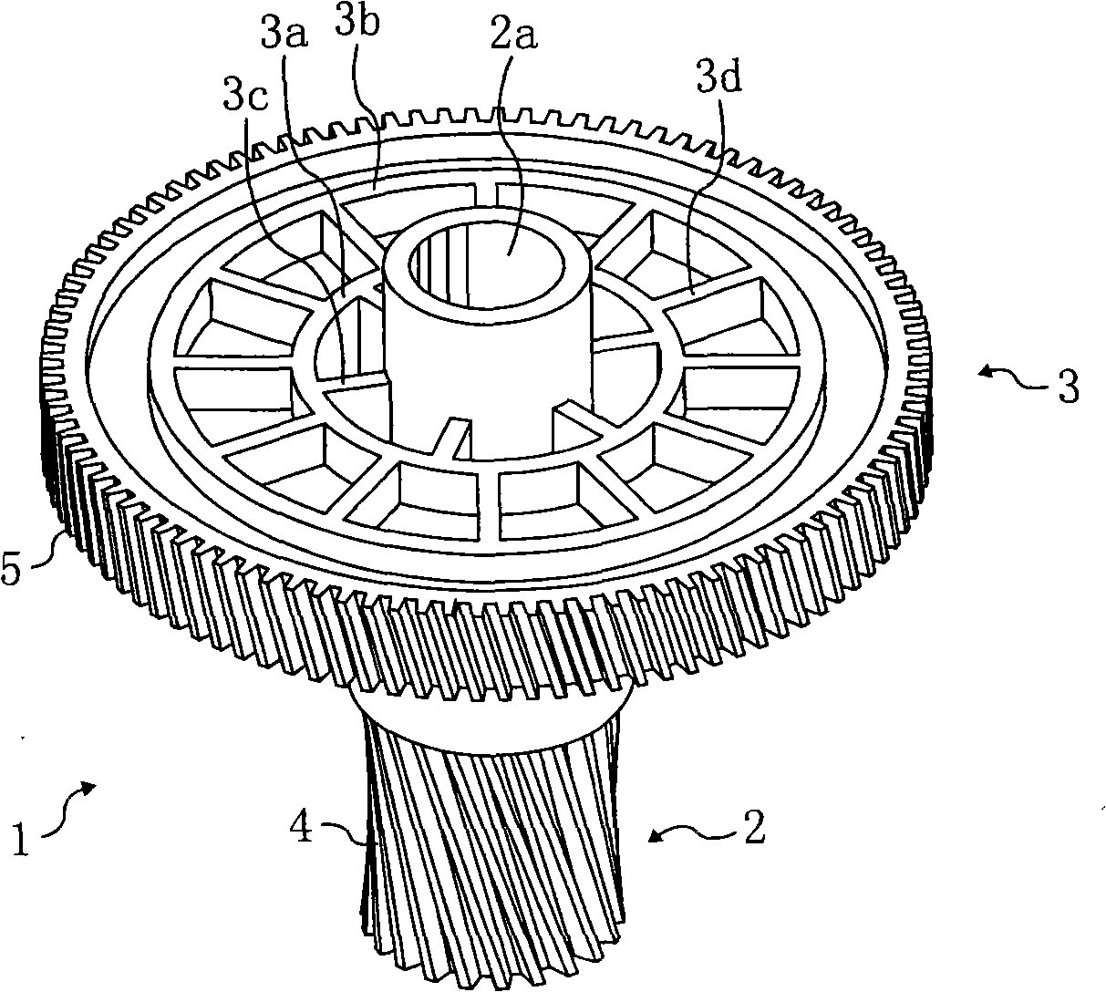
[0053] Figure 5 to Figure 7 A cross-sectional view of a molding die 30 for a two-layer resin helical gear having a gear portion in which the edge of the rotating shaft portion is integrally formed with the flange in the present invention is shown. Figure 5 It is a figure of the state of the molding die 30 of the present invention when the mold is closed, Figure 6 In order to make a resin helical gear as a resin helical gear with the molding die 30 of the present invention in a state when the mold is opened immediately after molding, Figure 7 It is a view showing the state of the resin helical gear produced by the molding die 30 of the present invention when it is released from the mold.

[0054] Above-mentioned molding die 30 is used for forming figure 1 and the helical gear 1 of the resin helical gear shown in FIG. 2 . The molding die 30 is composed of a fixed die 31 and a movable die 32 as a pair of split dies. The fixed mold 31 and the movable mold 32 cooperate to f...

Embodiment 2

[0071] Figure 9 A cross-sectional view of a three-layer resin helical gear molding die 50 having a pinion portion, that is, a gear portion in which the edge of the rotating shaft portion and the inner diameter flange are integrally formed in the clamped state, is shown. The die piece 51 forming the pinion gear portion, and the die piece 53 forming the middle gear portion having the structure of a connecting plate 52 connecting the edge of the middle gear portion and the inner diameter flange are located in the movable mold 65 of the mold. Furthermore, the die piece 54 forming the large diameter portion which is the large gear portion on the outside is located in the fixed die 66 of the mold. In the mold structure described above, since the distance between the pinion gear portion and the gate 55 becomes longer, the difference in resin filling time among the respective gear portions becomes smaller.

[0072] When opening the mold, the mold piece 54 rotates together with the r...


PUM


Abstract

The invention provides a molding die which, with a simple structure, forms a resin helical gear having a high precision helical gear part, more particularly a molding die (30) for forming the resin helical gear, comprising a large diameter part whose diameter is larger than that of a rotary shaft part, the helical gear parts are respectively formed at outer circumferential part of the large diameter part and at the rotary shaft part, the large diameter part forms a connection plate between the outer circumferential part thereof and the rotary shaft part; the molding die (30) is composed by an immovable die (31) and a movable die (32) which cooperatively form a die cavity (33') corresponding to the shapes of the large diameter part and the rotary shaft part; a rotating sheet is provided rotatably in the immovable die (31) to form the die cavity corresponding to the gear part formed on the outer circumferential part of the large diameter part; a die sheet (35) is provided in the movable die (32) to form the die cavity corresponding to the gear part formed on the outer circumferential part of the rotary shaft part; an entrance position (37) for molding the melting resin into a gate (36) in the mold cavity is provided at a position in the immovable die (31) away from each gear parts.

Description

technical field [0001] The present invention relates to a molding die for a resin helical gear and an improvement technique for a resin helical gear formed using the molding die. Background technique [0002] Regarding resin helical gears such as figure 1 The resin helical gear of the shown double-layer gear structure is composed of a rotating shaft portion 2 , that is, a boss, and a large diameter portion 3 . The large-diameter portion 3 is coaxial with the rotating shaft portion 2 , and its diameter is larger than that of the rotating shaft portion 2 . The rotating shaft portion 2 has a through hole 2a. [0003] One end of the rotating shaft portion 2 , that is, a tooth portion end of the rotating shaft portion 2 , has a spiral tooth portion 4 formed on the outer peripheral portion thereof. The large-diameter portion 3 is provided at the other end of the rotating shaft portion 2 , that is, at the end opposite to the tooth portion of the rotating shaft portion 2 . A hel...

Claims


Application Information

Patent Timeline
Patent Type & Authority Applications(China)
IPC IPC(8): B29C45/26B29C45/33B29C45/40F16H55/17B29L15/00
Inventor 小林孝次
Owner RICOH KK
Why Eureka
Try Eureka