A solar battery light collection cover

A technology of solar cells and daylighting covers, applied in optics, circuits, condensers, etc., can solve problems such as inability to effectively avoid output power reduction or damage, complex implementation, and low reliability, and achieve increased photoelectric conversion efficiency and photoelectric conversion efficiency. , enhance the effect of light intensity

Active Publication Date: 2008-09-17
BEIHANG UNIV
View PDF2 Cites 6 Cited by
  • Summary
  • Abstract
  • Description
  • Claims
  • Application Information

AI Technical Summary

Problems solved by technology

[0004] In order to improve the photoelectric conversion efficiency of solar cells, the domestic utility model patent "03223205.5 - Solar LED street lamp device" designed a new type of solar LED street lamp structure and transmission device, using a solar cell follower device, driven by a motor to follow the solar cell The sun rotates and rotates to achieve the highest conversion efficiency of solar cells; however, the system is more complicated to implement, the cost is higher, and the reliability is lower, and the motor control system needs maintenance and electric drive, and the overall efficiency is not high, so it is not suitable for small Solar battery system use
Since the traditional flat solar cell protection cover is still used, it cannot effectively avoid the heat island effect caused by the solar cell being partially blocked, which will reduce or damage the output power of the solar cell.
[0005] The utility model patent "01270896.8 - Solar Elevated Street Lighting Device" designed the overall structure of the elevated solar street light. The system uses a quasi-ellipsoidal plexiglass cover as the protective cover for the solar cells, which effectively prevents the solar cells from being blocked alone (such as leaves, bird droppings, etc.) ) will cause permanent damage to solar cells; the solar cells in this system are installed horizontally, which cannot solve the problem of low photoelectric conversion efficiency of solar cells when the incident angle of sunlight is small

Method used


Image

  • A solar battery light collection cover
  • A solar battery light collection cover
  • A solar battery light collection cover

Examples


Embodiment Construction

[0021] The present invention will be described in detail below in conjunction with the accompanying drawings and specific embodiments.

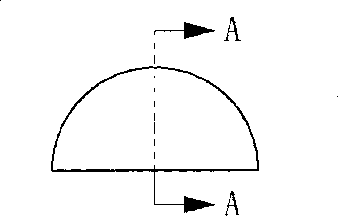
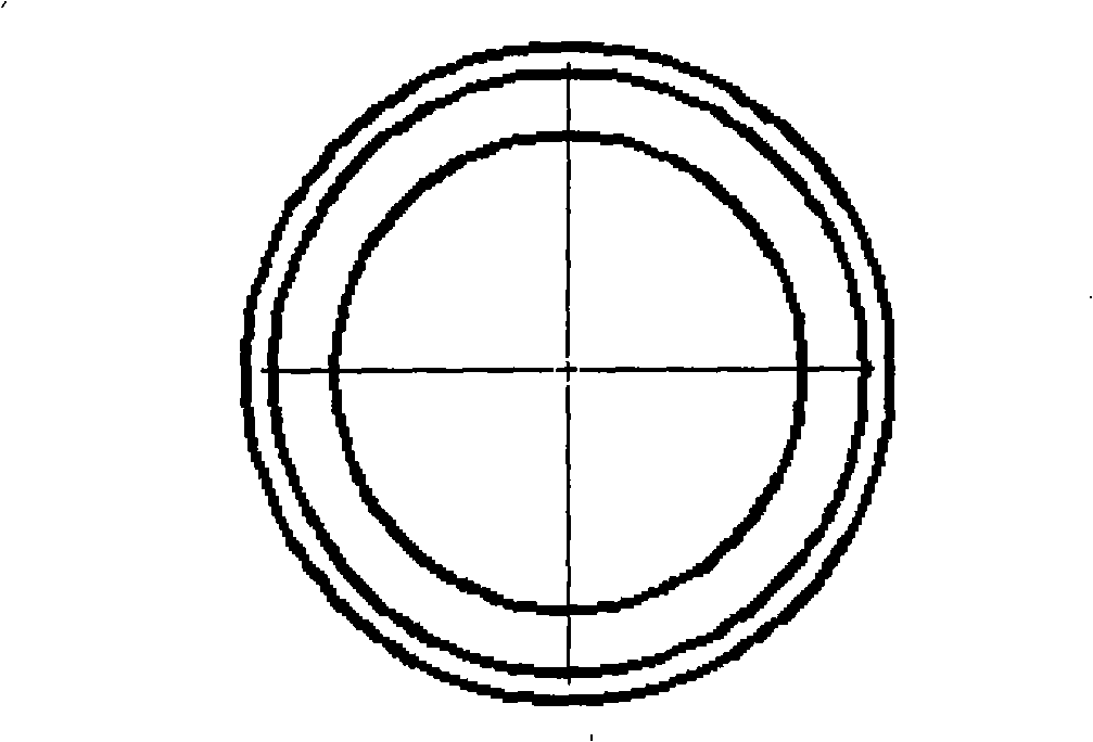
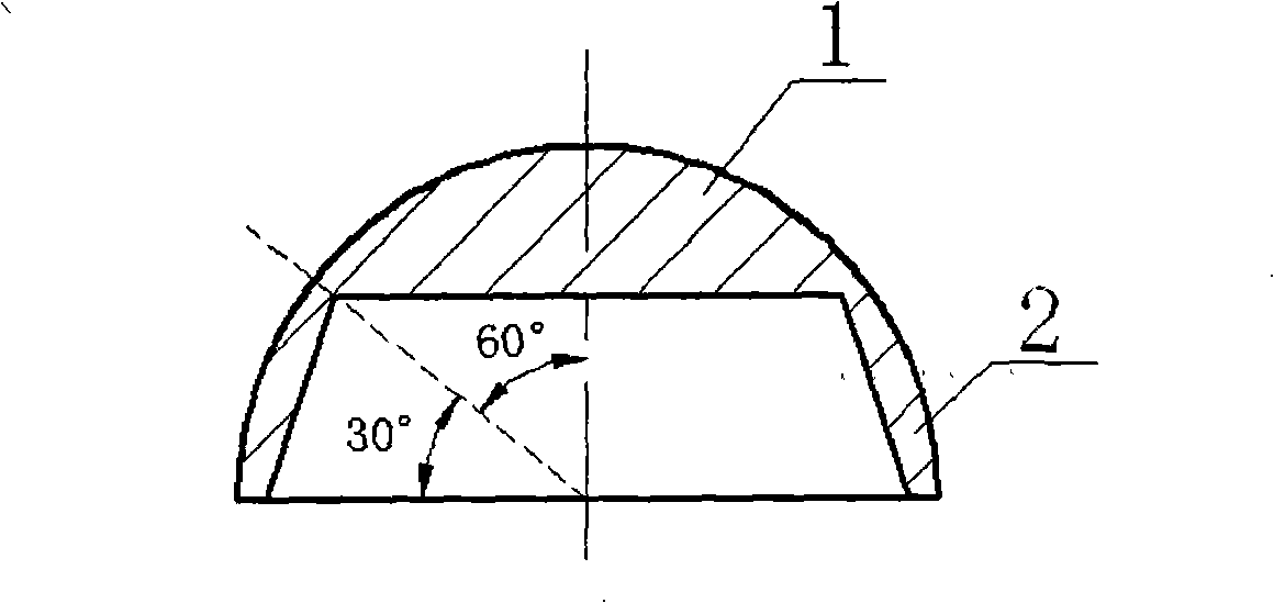
[0022] A solar battery lighting cover of the present invention is composed of a central lighting lens 1 and an annular lighting lens 2. The central lighting lens 1 adopts a plano-convex lens structure; the annular lighting lens 2 adopts an annular lens structure with a certain height, and the central lighting lens 1 is located in a Above the lighting lens 2, and the size of the circular section surrounded by the lower surface of the central lighting lens 1 and the upper edge of the annular lighting lens 2 is consistent, ensuring that they can be connected together in good condition, and the annular lighting lens 2 section is also It is a plano-convex lens; the shape of the solar cell daylighting cover of the present invention is a spherical shell shape, and its front view is as figure 1 As shown, the bottom view is as figure 2 As shown, the...


PUM


Abstract

A solar battery lighting cover comprises a central lighting lens and a ring-shaped lighting lens, in characterized that the central lighting lens uses a flat convex lens structure, the ring-shaped lighting lens uses a ring-shaped lens structure with a certain of height, the central lighting lens is disposed above the ring-shaped lighting lens, the lower surface of the central lighting lens has the same size with the round cross-section enclosed by upper edge of the ring-shaped lighting lens; the cross-section of the ring-shaped lighting lens also uses a flat convex lens; when being used, the solar battery lighting cover according to the invention can use the central lighting lens to focus the light when the solar incident angle is greater than or equal to 30 degree, in order to enhance the lighting efficiency; use the light refraction from the ring-shaped lighting lens to obtain sufficient light when the solar incident angle is less than 30 degrees, in order to generate power; meanwhile, the solar lighting cover according to the invention can avoid the problem of low efficiency or even damage resulted from being partially covered.

Description

technical field [0001] The invention relates to an optical device, in particular to a solar cell daylighting cover. Background technique [0002] A solar cell is a device that responds to light and converts light energy into electricity. There are many materials that can produce photovoltaic effects, such as: single crystal silicon, polycrystalline silicon, amorphous silicon, gallium arsenide, indium selenium copper, etc. , their power generation principles are basically the same, and the crystal is used as an example to describe the photovoltaic power generation process. P-type crystalline silicon can be doped with phosphorus to obtain N-type silicon, forming a P-N junction. When the light irradiates the surface of the solar cell, some photons are absorbed by the silicon material; the energy of the photons is transferred to the silicon atoms, causing the electrons to migrate and become free electrons to gather on both sides of the P-N junction to form a potential differenc...

Claims


Application Information

Patent Timeline
Patent Type & Authority Applications(China)
IPC IPC(8): H01L31/0232H01L31/052G02B19/00H01L31/055
CPCY02E10/52
Inventor 郑德智汤鹏翔张欲晓
Owner BEIHANG UNIV
Why Eureka
Try Eureka