Stacked photovoltaic device

a photovoltaic device and stacked technology, applied in the field of stacked photovoltaic devices, can solve the problems of high production cost, ineffective use of short-wavelength components, and inability to effectively utilize short-wavelength components

Inactive Publication Date: 2005-02-10
CANON KK
View PDF11 Cites 57 Cited by
  • Summary
  • Abstract
  • Description
  • Claims
  • Application Information

AI Technical Summary

Problems solved by technology

However, since the production of such photovoltaic devices makes use of the semiconductor production process as stated above, it requires a high production cost.
The single-crystal silicon photovoltaic devices have additional disadvantages that the single-crystal silicon has a small optical absorption coefficient because of its indirect transition and hence must be formed in a thickness of at least 50 im in order to absorb more sunlight, and that it has a band gap of about 1.1 eV, which is narrower than 1.5 eV suited for photovoltaic devices, and hence can not utilize short-wavelength components effectively.
Even if polycrystalline silicon is used to achieve a cost reduction, the problem of indirect transition still remains and the photovoltaic devices can not be made to have a smaller thickness.
In addition, polycrystalline silicon also ha

Method used


Image

  • Stacked photovoltaic device
  • Stacked photovoltaic device
  • Stacked photovoltaic device

Examples


example 1

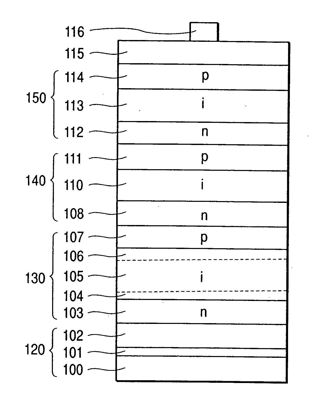
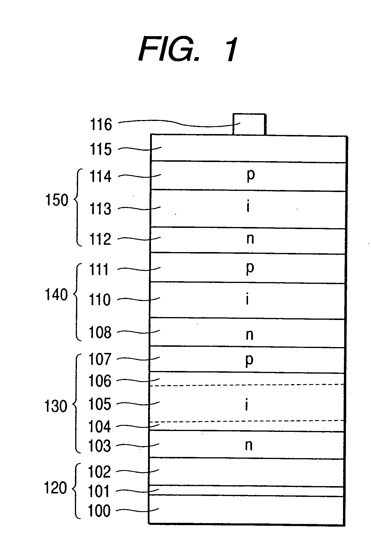
[0159] The stacked photovoltaic device as shown in FIG. 1 was produced using a deposition system shown in FIG. 4. A deposition system 400 can carry out both of MWPCVD and RFPCVD. Using this deposition system 400, the respective semiconductor layers were formed on a substrate 490 having light-reflecting layers 101 and 102.

[0160] To the deposition system, material gas cylinders (not shown) are connected through gas feed pipes. The material gas cylinders contain all purified gases in an ultra-high purity, and an SiH4 gas cylinder, a CH4 gas cylinder, a GeH4 gas cylinder, an Si2H6 gas cylinder, a PH3 / H2 (dilution: 2.0%) gas cylinder, a B2H6 / H2 (dilution: 2.0%) gas cylinder, an H2 gas cylinder, an He gas cylinder, an SiCl2H2 gas cylinder and an SiH4 / H2 (dilution: 2%) gas cylinder were connected.

[0161] Next, the substrate 490, on which a metal layer 101 and a transparent conductive layer 102 had been formed, was placed on a substrate transporting rail 413 provided in a load chamber 401,...

example 2

[0205] A photovoltaic device was produced in the same manner as in Example 1 except that the third p-i-n, i-type layer 105 comprised of ic-Si was formed by changing the frequency of the microwaves to 0.1 GHz.

[0206] The substrate heater 411 was set so as to bring the temperature of the substrate 490 to 330° C. At the time the substrate was heated well, the valves 461, 451, 450, 463 and 453 were opened slowly to flow SiH4 gas and H2 gas into the i-type layer deposition chamber 418 through the gas feed pipe 449.

[0207] Here, SiH4 gas flow rate and H2 gas flow rate were controlled by means of the corresponding mass flow controllers 456 and 458 so as to be 60 sccm and 2,400 sccm, respectively. The pressure inside the i-type layer deposition chamber 418 was controlled so as to be 0.2 Torr by adjusting the opening of the conductance valve (not shown).

[0208] Next, the power of a microwave power source (not shown; 0.1 GHz) was set to 0.15 W / cm3, and was applied to the bias rod 428 to cause...

example 3

[0214] In Example 1, to form the second p-i-n, i-type layer 110 comprised of ic-Si, SiH4 gas flow rate and H2 gas flow rate were controlled by means of the corresponding mass flow controllers 456 and 458 so as to be 70 sccm and 2,100 sccm, respectively. The pressure inside the i-type layer deposition chamber 418 was controlled so as to be 0.05 Torr by adjusting the opening of the conductance valve (not shown).

[0215] Next, the power of the RF power source 424 was set to 0.15 W / cm3, and was applied to the bias rod 428. Thereafter, the power of a microwave power source (not shown; 0.5 GHz) was set to 0.12 W / cm3, and microwave power was fed into the i-type layer deposition chamber 418 through the bias rod 428 to cause glow discharge to take place. Thus, the second p-i-n, i-type layer was started being formed on the second p-i-n, RF n-type layer, and an i-type with a layer thickness of 1.0 im was formed, whereupon the glow discharge was stopped and the output from the bias power source ...


PUM


Abstract

[Problem(s)] A stacked photovoltaic device can be provided which is practicable and low-cost and yet has a high reliability, and also has a high photoelectric conversion efficiency. [Means for Solving the Problem] A stacked photovoltaic device comprises at least three p-i-n junction constituent devices superposed in layers, each having a p-type layer, an i-type layer and an n-type layer which are formed of silicon type non-single-crystal semiconductors. An amorphous silicon is used as the i-type layer of a first p-i-n junction, a microcrystalline silicon is used as the i-type layer of a second p-i-n junction and a microcrystalline silicon is used as the i-type layer of a third p-i-n junction, the first to third layers being in the order from the light-incident side.

Description

DETAILED DESCRIPTION OF THE INVENTION [0001] 1. Field of the Invention [0002] This invention relates to a stacked photovoltaic device such as a solar cell and a photosensor, formed by superposing at least three p-i-n junction constituent devices each having a p-type layer, an i-type layer and an n-type layer which are formed of silicon type non-single-crystal semiconductors. [0003] 2. Prior Art [0004] Photovoltaic devices which are photoelectric conversion devices that convert sunlight into electric energy are put into wide use as public-purpose power sources for low-power supply such as electronic calculators and wrist watches, and attract notice as practicable technique in future as substitute power for what is called petroleum fuel such as oil and coal. [0005] Photovoltaic devices concern a technique that utilizes photovoltaic force attributable to p-n junction of semiconductor devices. Semiconductors such as silicon absorb sunlight to produce photocarriers of electrons and holes...

Claims


Application Information

Patent Timeline
IPC IPC(8): H01L31/04H01L31/06H01L31/076H01L31/077H01L31/18H01L31/20
CPCH01L31/076H01L31/1816H01L31/1824Y02E10/548H01L31/206Y02E10/545H01L31/202Y02E10/547Y02P70/50
Inventor SANO, MASAFUMINAKAMURA, TETSURO
Owner CANON KK
Why Eureka
Try Eureka