Shunting injection allocation method and shunting injection allocation machine

A dispenser and dispensing technology, which is used in the production of fluids, earth-moving drilling, wellbore/well components, etc., can solve problems such as reduction and large molecular weight of polymers, and achieve enhanced oil recovery, small shearing action, The effect of reduced losses

Active Publication Date: 2011-10-05
CHINA NAT OFFSHORE OIL CORP +1
View PDF4 Cites 0 Cited by
  • Summary
  • Abstract
  • Description
  • Claims
  • Application Information

AI Technical Summary

Problems solved by technology

In the work of enhancing oil recovery by polymer injection (abbreviation of polymer flooding) in offshore oilfields, due to the high molecular weight of the injected polymer, it is hoped that the shear band caused by high-speed flow should be avoided as much as possible in the injection string and at the nozzle. The reduction of the viscosity of the coming polymer stream, but there is no mature product supply in the market

Method used


Image

  • Shunting injection allocation method and shunting injection allocation machine
  • Shunting injection allocation method and shunting injection allocation machine
  • Shunting injection allocation method and shunting injection allocation machine

Examples


Embodiment Construction

[0012] The present invention will be described in detail below in conjunction with the accompanying drawings and embodiments.

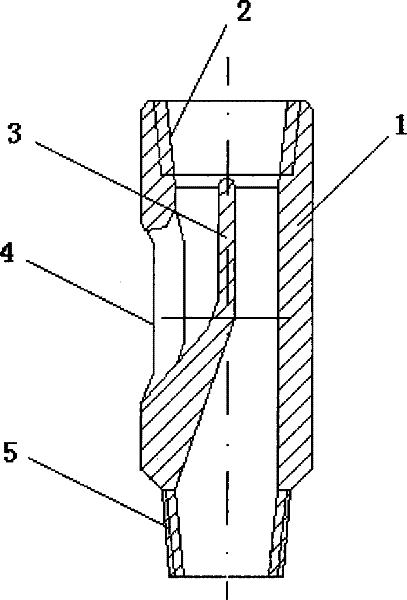
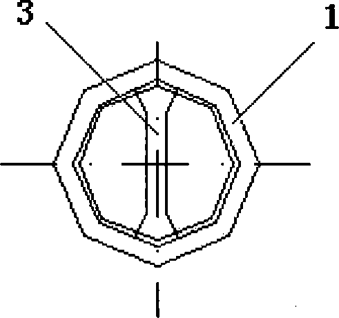
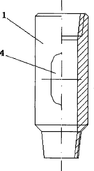
[0013] Such as Figure 1~3 As shown, the present invention includes a cylindrical dispenser body 1, a tapered internal thread interface 2 is provided on the upper part of the dispenser body 1, and a smooth-surface shunt barrier 3 is provided at the lower part of the internal thread interface 2. The lower part of the divider barrier 3 is inclined to one side of the inner wall of the dispenser body 1 and smoothly connected with it, thereby dividing the inner cavity of the dispenser body 1 into two parts, one part of which is connected to the outlet 4 on the side of the dispenser body 1 The other part communicates with the tapered external thread interface 5 provided at the lower part of the dispenser body 1 .

[0014] Such as Figure 4 As shown, when the present invention is used, the internal thread interface 2 on the upper part of the dispenser body...


PUM


Abstract

The invention relates to a split-flow injection allocation method and a split-flow distributor. The method of the invention is characterized in that every subsection of a polymer injection pipe is provided with at least one distributor, and a split-flow barrier is arranged in the distributor to divide polymeric liquid entering into the distributor into two parts, one part of which flows up to an upper oil reservoir and the other part of which continues to flow down to the lower oil reservoir. The polymer injection pipe is provided with the split-flow distributor and the surface of the split-flow distributor is sleekly connected with the outlet of the distributor. So liquid passing by the distributor has little partial drop pressure loss, low friction resistance and little shearing action,thus effectively reducing the loss of the viscosity of injected polymer. The split-flow injection allocation method and the split-flow distributor can be widely used for improving the recovery ratio of reservoir oil displacement in an offshore oilfield.

Description

technical field [0001] The invention relates to a flow diversion method and device, in particular to a flow diversion distributing method and a diversion distributor used for polymer flooding in offshore oil field exploitation. Background technique [0002] In order to improve the recovery efficiency of existing oilfields in offshore oilfields, the method of injecting polymer flooding is usually used to solve the problem, so as to achieve the purpose of improving recovery and increasing oilfield production. Polymer flooding technology is to inject chemical polymers into oil layers, dilute the viscosity of crude oil through the chemical effect of polymers, decompose water, and squeeze or absorb crude oil stored in complex oil layers that is difficult to recover, so as to facilitate centralized recovery by oil recovery machines. In the work of enhancing oil recovery by polymer injection (abbreviation of polymer flooding) in offshore oilfields, due to the high molecular weight ...

Claims


Application Information

Patent Timeline
Patent Type & Authority Patents(China)
IPC IPC(8): E21B43/20
Inventor 姜伟刘义刚张健牛海峰付英军
Owner CHINA NAT OFFSHORE OIL CORP
Why Eureka
Try Eureka