Normalization alignment mark combination and its alignment method and alignment system

An alignment mark and alignment system technology, applied in optics, instruments, photolithography process of pattern surface, etc., can solve the problems of large light transmission area, small capture range, large detection imaging energy density, etc., to improve stability Sexual accuracy, increased capture capability, improved detection capability

Active Publication Date: 2008-09-24
SHANGHAI MICRO ELECTRONICS EQUIP (GRP) CO LTD
View PDF6 Cites 13 Cited by
  • Summary
  • Abstract
  • Description
  • Claims
  • Application Information

AI Technical Summary

Problems solved by technology

[0006] In the previous above-mentioned devices, due to the large and concentrated light transmission area of ​​the single-hole-shaped normalized alignment mark on the patterning part, there is a problem that the detection and imaging energy density is relatively large, and its detection and capture range is relatively small, especially The flat top and trapezoidal slope section of the alignment scanning signal are short. When the scanning speed is high, the number of sampling points in this section is insufficient, which is not conducive to meeting the accuracy requirements of alignment scanning positioning and rough capture. If you need to add enough sampling points , on the one hand, the alignment scanning speed can be reduced, but this will reduce the throughput of the lithography device; on the other hand, the size of the single-hole-shaped normalized alignment mark on the target patterning part can be increased, but the imaging area is increased , which is not conducive to improving the stability accuracy of the alignment scan
[0007] For conventional porous-shaped normalized alignment marks, on the one hand, there are the above-mentioned problems, and on the other hand, there are multi-step alignment scan signals or convex / concave inflection points in the alignment scan signal, which are not conducive to improving the normalization. Accuracy and adaptability requirements of alignment scanning
[0008] In addition, the above-mentioned single-well-shaped normalization alignment markers and conventional multi-well-shape normalization alignment markers have a smaller capture range

Method used


Image

  • Normalization alignment mark combination and its alignment method and alignment system
  • Normalization alignment mark combination and its alignment method and alignment system
  • Normalization alignment mark combination and its alignment method and alignment system

Examples


Embodiment Construction

[0029] The normalized alignment mark combination of the present invention and its alignment method and alignment system will be further described in detail below.

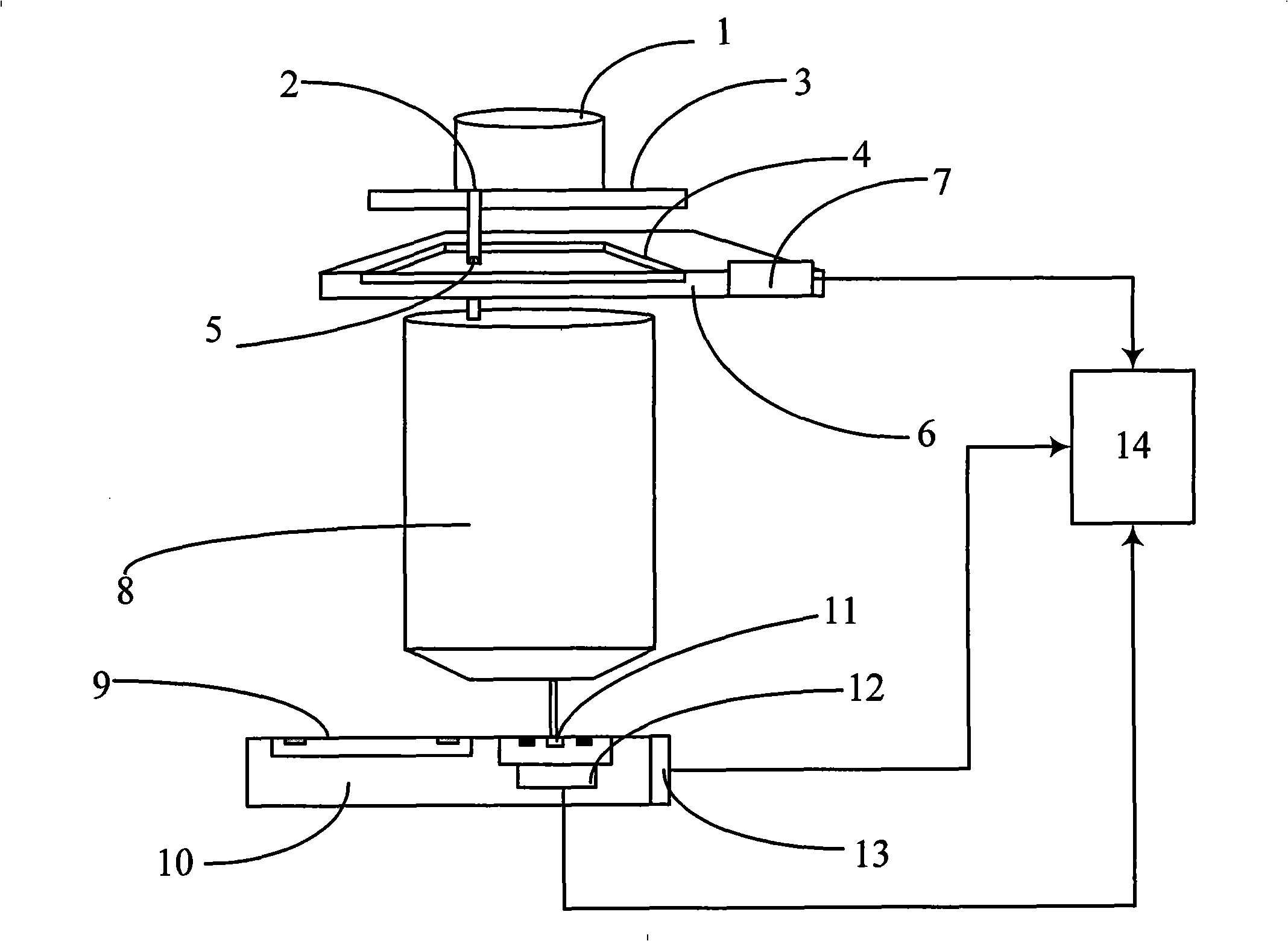
[0030] figure 1 It is a structural schematic diagram of a lithographic equipment alignment system applying the normalized alignment mark combination and its alignment signal processing method of the present invention. and alignment patterning figure 5); detection patterning part, it is positioned on the same plane with lithography workpiece 9, and has detection patterning part mark 11 on the said detection patterning part, has radiation spatial pattern detection device 12 below it; Target patterning part The carrying platform 6 and its position measuring device 7; the detecting patterning part carrying platform 10 and its position measuring device 13; the projection system 8 and the alignment signal processing device 14 placed between the target patterning part 4 and the detecting patterning part. The working prin...


PUM


Abstract

The invention discloses an uniformization aligning mark combination and an aligning method and an aligning system thereof. The uniformization aligning mark combination consists of a porous uniformization aligning mark arranged at the target composing component of a photoetching device aligning system and a single-pore uniformization aligning mark arranged at a probe composing component. The porous uniformization aligning mark consists of four transparent elements and a chromeplated shielding layer. The single-pore uniformization aligning mark consists of a transparent element and a chromeplated shielding layer. The method uses the single-pore uniformization aligning mark at the probe composing component and a probe device under the single-pore uniformization aligning mark to process twice two-dimensional aligning scanning to an image formed by the porous uniformization aligning mark at the target composing component, and radiation measure information and position measure information obtained by the two times of canning are integrated for an aligning signal processing, which obtains the position relation of a space image formed by the target composing component at a target composing component bearing table through a projection system relative to a probe composing component bearing table.

Description

technical field [0001] The invention relates to an alignment scanning method of a lithographic equipment, in particular to a method for aligning and scanning the porous shape normalized alignment of the lithographic equipment. Background technique [0002] In industrial devices, due to the need for high precision and high productivity, a large number of detection devices and control systems for high-speed real-time measurement, signal sampling, data acquisition, data exchange and communication transmission are distributed. These systems require us to use various methods to realize the control of detection, signal sampling control, data acquisition control, data exchange control and data transmission communication. Devices that require detection and control include: integrated circuit manufacturing lithography equipment, flat panel display panel lithography equipment, MEMS / MOEMS lithography equipment, advanced packaging lithography equipment, printed circuit board lithography...

Claims


Application Information

Patent Timeline
Patent Type & Authority Applications(China)
IPC IPC(8): G03F7/20G03F9/00
Inventor 李焕炀宋海军胡明辉严天宏周畅
Owner SHANGHAI MICRO ELECTRONICS EQUIP (GRP) CO LTD
Why Eureka
Try Eureka