
Road lamp inspection device and method

A detection device and street lamp technology, applied in lighting devices, lamp testing, lamp circuit layout, etc., can solve problems such as inability to accurately detect and control, inability to determine the specific location of the fault point, inconvenient system operation and maintenance, etc., to ensure accuracy Effect

Inactive Publication Date: 2008-09-24
SHANGHAI MINHANG HIGH SCHOOL +1
View PDF1 Cites 16 Cited by
  • Summary
  • Abstract
  • Description
  • Claims
  • Application Information

AI Technical Summary

Problems solved by technology

[0003] Most of the existing control technologies control the switching of multiple lights and all the lights on a certain road through intermediate-level road section control equipment, and at the same time perform line-level state detection. Only when a certain number of lights are not on at the same time or other When there is a fault, it is only possible to detect and judge that there is a fault in the street lamp circuit, and the specific location of the fault point cannot be determined, that is, the detection and control of each lamp (lighting unit) cannot be accurately detected, which will have a negative impact on the operation and maintenance of the entire system. inconvenient

Method used


Image

  • Road lamp inspection device and method

Examples


Embodiment Construction

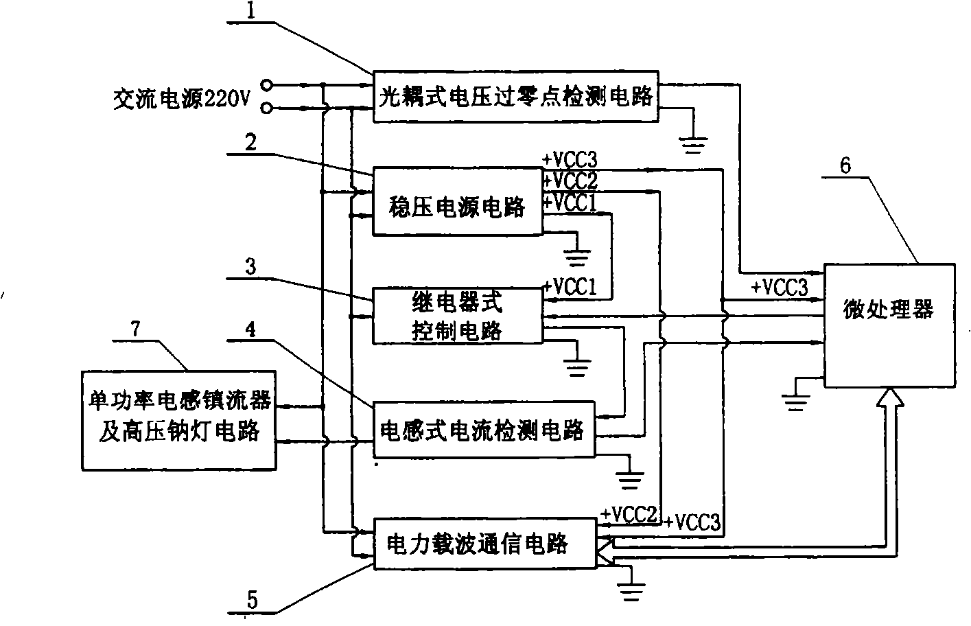
[0017] The invention provides a street lamp detection device, which mainly detects the ballast of the street lamp, and its main structure is similar to that of the existing devices (such as figure 1 ) are basically similar. For example: the detection device is composed of an optocoupler voltage zero-crossing detection circuit, a regulated power supply circuit, a relay control circuit, an inductive current detection circuit, a power carrier communication circuit, and a microprocessor. Among them: one input terminal of the optocoupler voltage zero-crossing detection circuit, one input terminal of the regulated power supply circuit, and the relay is the input terminal of the control circuit connected to one input terminal of the power carrier communication circuit and connected to one end of the AC power supply 220V, The other input terminal of the type voltage zero-crossing detection circuit, the other input terminal of the regulated power supply circuit, but one power supply in...


PUM


Abstract

The invention provides a detection device for street lights, which mainly detects the ballast of the street lights. The detection device consists of a detection circuit of an optical coupled voltage passing zero point, a stabilivolt source circuit, a controlling circuit with a relay, an inductance current detection circuit, a power carrier wave communication circuit and a microprocessor. The detection and controlling device adopts a simulated resistance load. When the device is used for detecting, the steps are as follows: A. the sine wave of an ac power is divided into four sections; B. the inductance current detection circuit carries out continuous sampling measurement in sequence; C. the result in the step B is subject to summation and then is compared; D. the result is transmitted to a monitoring center through the power carrier wave communication circuit. The device and method in the invention can fast and exactly detect all input and output parameters of the ballast and judge the quality of the ballast. The detection steps and the output types can be automatically combined for adapting to the measurement of different ballasts. The system error can be automatically corrected for ensuring the accuracy of the tested data.

Description

technical field [0001] The invention relates to the technical field of detecting street lamps in use, in particular to a street lamp detecting device and a detecting method. Background technique [0002] As we all know, the main cause of street lamp failure is the failure of the ballast. The ballast has two functions: one is to generate a high induced voltage when the fluorescent lamp starts to ignite the lamp, and the other is to limit the current passing through the lamp when the lamp is working so as not to burn the filament. The general ballast has only two connectors, and there is another ballast with four connectors. The working principle of this ballast is basically the same as that of the two connectors, except that a set of auxiliary coils (secondary coils for short) is added. , the auxiliary coil assists the main coil to complete the starting work, so that the performance of the ballast is further improved. [0003] Most of the existing control technologies contr...

Claims


Application Information

Patent Timeline
Patent Type & Authority Applications(China)
IPC IPC(8): H05B41/00H05B37/03G01R31/24G01R31/44
CPCY02B20/72
Inventor 项敏杨阳
Owner SHANGHAI MINHANG HIGH SCHOOL
Learn More