
Driving and regulating method and device for bipolar transistor in electric ballast

一种电子镇流器、双极晶体管的技术,应用在照明装置、电光源、电气元件等方向,能够解决不可用等问题,达到降低功率消耗、控制方法与控制装置灵活、降低电源电流的效果

Inactive Publication Date: 2008-09-24
PATENT TREUHAND GESELLSCHAFT FUER ELECTRIC GLUEHLAMPEN M B H
View PDF0 Cites 8 Cited by
  • Summary
  • Abstract
  • Description
  • Claims
  • Application Information

AI Technical Summary

Problems solved by technology

However, this control logic is only useful during normal operation, not during warm-up and during ignition

Method used


Image

  • Driving and regulating method and device for bipolar transistor in electric ballast
  • Driving and regulating method and device for bipolar transistor in electric ballast
  • Driving and regulating method and device for bipolar transistor in electric ballast

Examples


Embodiment Construction

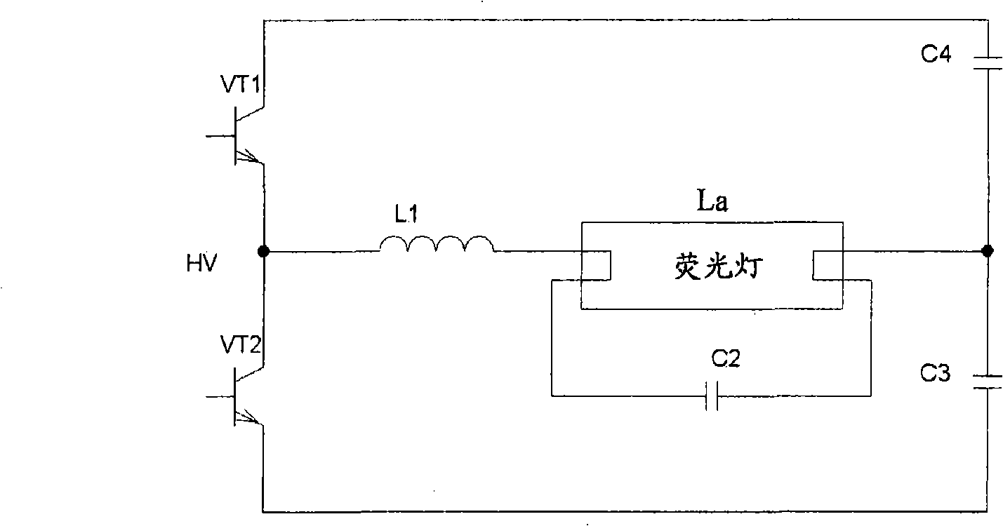
[0015] Such as figure 1 As shown, the power circuit of an electronic ballast is given. Transistors VT1, VT2, resonant inductor L1, resonant ignition capacitor C2, half-bridge capacitors C3, C4 and load La (ie fluorescent lamp) form a classic electronic ballast Half bridge resonant circuit.

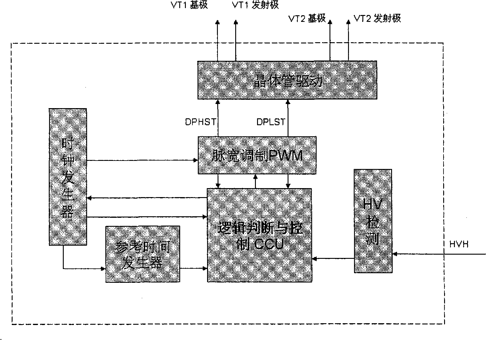
[0016] figure 2 A structural block diagram of the bipolar transistor drive adjustment device in the electronic ballast according to the present invention is given, and the arrows in the figure indicate the signal flow direction. The entire control circuit includes the following parts, HV detection ( HV S ense-HVS) unit, logic judgment and control (CCU) unit, clock generator (Timer) unit, reference time generator ( R eference T imer-RT) unit, pulse width modulation (PWM) unit, and transistor driving unit (Transistors Driving-TD). Its functions are described as follows:

[0017] HV detection unit ( HV S ense-HVS)

[0018] The HV detection unit detects the voltage HV at the midpo...


PUM


Abstract

The invention discloses a driving and adjusting method of a bipolar transistor in an electronic ballast and a device thereof, which comprises the following steps: a detection step is used for detecting the voltage of the half-bridge middle point of the transistor; a step is used for generating a reference time signal; a step is used for generating a time interval; a comparison step is used for carrying out comparison between the real time interval and the reference time signal for determining the pulse width of a driving signal; and an adjusting step, if the real time interval is larger than the reference time signal, the driving signal of the period is prolonged relative to the driving signal of the last switch period; if the real time interval is smaller than the reference time signal, the driving signal of the period is shortened relative to the driving signal of the last switch period. The controlling method and the controlling device according to the technical proposal of the invention are flexible enough, the transistor can be driven and switched in the whole working period of the ballast and the transistor can be kept in a soft switching state in all working frequency. The controlling method is in favor of reducing and controlling the power consumption and power current of the ASIC.

Description

technical field [0001] The present invention relates to a method and a device capable of driving bipolar transistors in a half-bridge topology for electronic ballasts and electronic transformers. Background technique [0002] Fluorescent lamps and high-intensity gas discharge lamps have many advantages such as high luminous efficiency, long life and wide power range, so they occupy an important position in the current lighting field. During lighting of fluorescent and high-intensity discharge lamps, light is produced when a beam of electrons passes through a gaseous medium. And the lighting of this kind of lamp needs to use the ballast. Due to their high efficiency, small size and flexible control, electronic ballasts have increasingly replaced traditional inductive ballasts. [0003] How to drive bipolar transistors in half-bridge topologies used in electronic ballasts and electronic transformers to maintain soft switching at any operating frequency has important implicat...

Claims


Application Information

Patent Timeline
Patent Type & Authority Applications(China)
IPC IPC(8): H05B41/28
CPCH05B41/2828
Inventor 高炜
Owner PATENT TREUHAND GESELLSCHAFT FUER ELECTRIC GLUEHLAMPEN M B H
Learn More