Rolling mill oil film bearing

A technology of oil film bearings and bearings, which is applied in the direction of bearings, metal rolling stands, metal rolling mill stands, etc., and can solve problems such as increased weight

Inactive Publication Date: 2008-10-01
PRIMETALS TECH USA
View PDF0 Cites 16 Cited by
  • Summary
  • Abstract
  • Description
  • Claims
  • Application Information

AI Technical Summary

Problems solved by technology

Larger locking assembly weights (possibly in excess of 900 kg) can further exacerbate such problems

Method used


Image

  • Rolling mill oil film bearing
  • Rolling mill oil film bearing
  • Rolling mill oil film bearing

Examples


Embodiment Construction

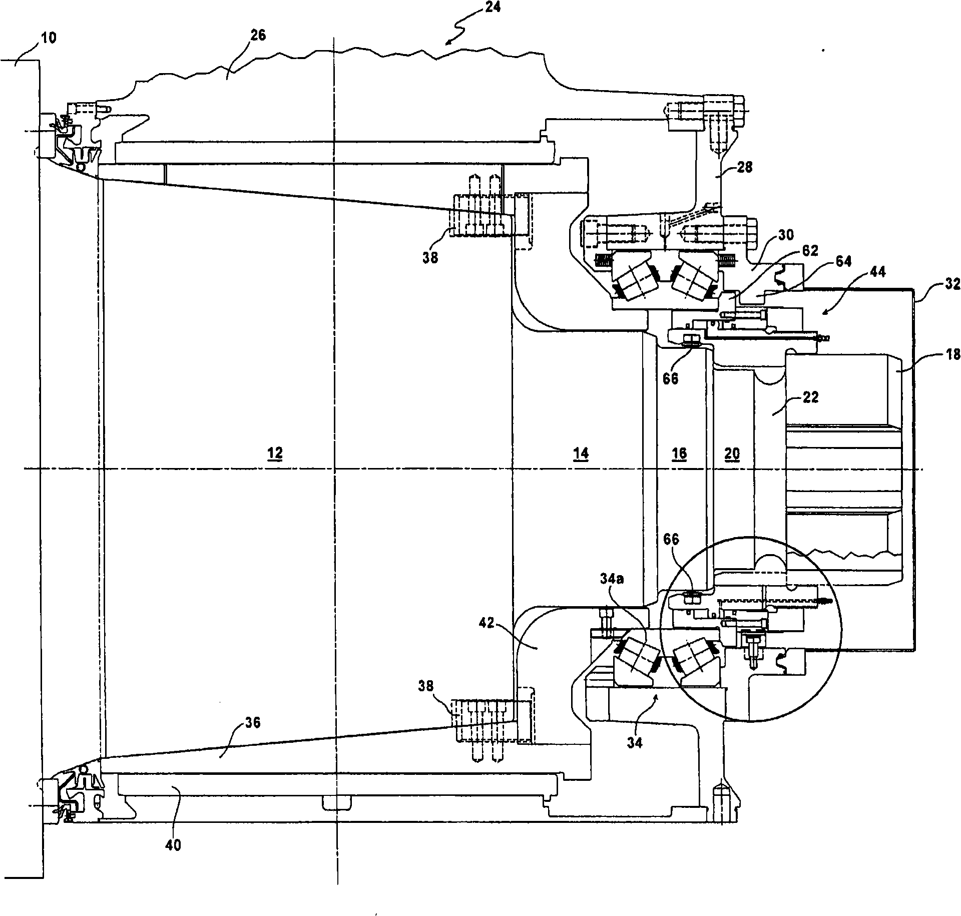
[0011] see first figure 1 , the rolling mill roll 10 has a conical section 12 leading to an end with a cylindrical middle section 14, 16 of reduced diameter, which is separated from the cylindrical end section 18 by a cylindrical section 20 and an annular groove 22 separated. The oil film bearing 24 includes a bearing housing 26 that cooperates with end plates 28 and 30 and a cover 32 to define a housing that contains a thrust bearing 34 and a sleeve bearing comprising a shaft rotatable by a key 38. Fixed to the sleeve 36 of the tapered neck section 12, the sleeve is rotatably journaled in the bushing 40 fixed in the bearing housing 26.

[0012] A thrust ring 42 is interposed between the sleeve 36 and the thrust bearing 34, and a locking assembly 44 cooperates with the inner race 34a of the thrust bearing 34 to retain the oil film bearing axially on the roll neck.

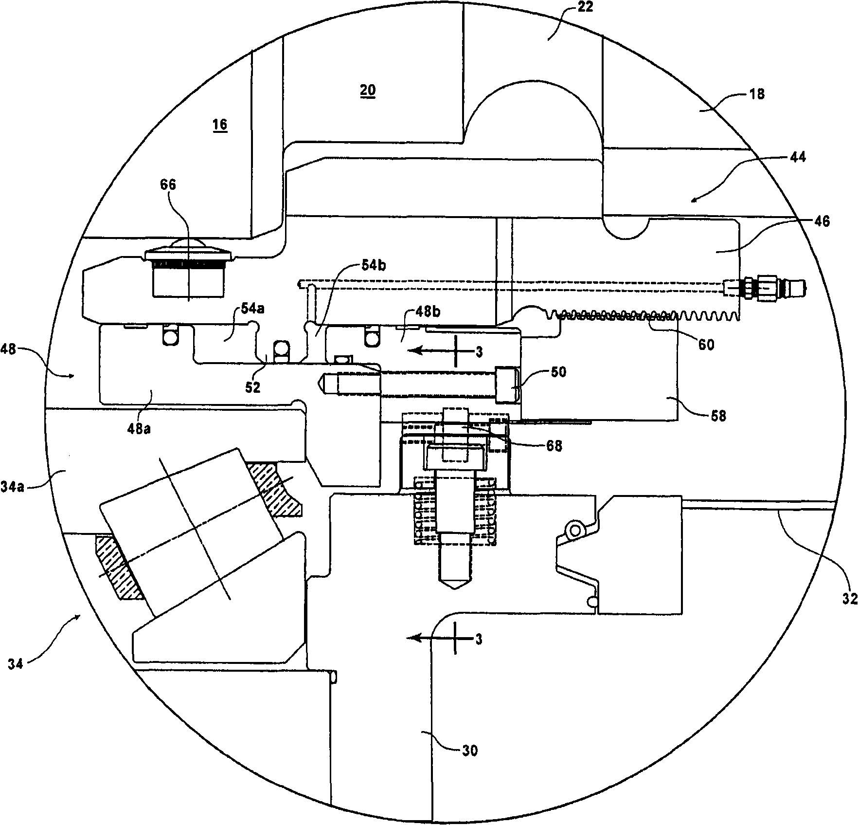
[0013] as seen by further figure 2 Whereas it is clearly seen, the locking assembly 44 includes a piston 46 ...


PUM


Abstract

An oil film bearing assembly rotatably supports the neck of a roll in a rolling mill. The bearing assembly comprises a housing containing a sleeve bearing and a thrust bearing. A circular lock assembly coacts with the thrust bearing to axially retain the bearing assembly on the roll neck. The lock assembly is axially received on and is rotatable into and out of mechanical interengagement with theroll neck. First bearing elements are carried by and project inwardly from the lock assembly to contact a surface of the roll neck at a first location, and second bearing elements project inwardly from the housing to contact an outer surface of the lock assembly at a second location spaced axially from the first location.

Description

technical field [0001] This invention relates generally to oil film bearings for rotatably supporting roll necks in rolling mills. Background technique [0002] Mill oil film bearings are usually held in place by locking assemblies that rotate in and out of mechanical interfit with the roll neck. In larger size bearings, such as those for rolls one and a half meters in diameter and larger, locking rotation would require a relatively large clearance between the cooperating roll neck and the surface of the locking assembly, which in turn would There is a tendency for the locking assembly to tilt, misalign and bind during installation and removal. Such problems are further exacerbated by the large locking assembly weight (possibly in excess of 900 kg). [0003] It is an object of the present invention to provide a mechanical interfit that includes strategically placed bearings to allow the locking assembly to be easily rotated in and out of the roll neck, such strategic place...

Claims


Application Information

Patent Timeline
Patent Type & Authority Applications(China)
IPC IPC(8): B21B31/07F16C13/02
CPCB21B31/074B21B31/08B21B31/07B21B31/00
Inventor P·N·奥斯古德A·S·马丁斯T·C·小沃特考瓦斯基E·L·乔纳森R·迪威基利奥
Owner PRIMETALS TECH USA
Why Eureka
Try Eureka