Angular velocity senor

a technology of angular velocity sensor and output characteristic, applied in the direction of acceleration measurement using interia force, turn-sensitive devices, instruments, etc., can solve the problems of reducing the output signal of the tuning fork portion and unstable and achieve the effect of stabilizing the output characteristic of the angular velocity sensor

Active Publication Date: 2007-06-26
PANASONIC CORP
View PDF15 Cites 13 Cited by
  • Summary
  • Abstract
  • Description
  • Claims
  • Application Information

AI Technical Summary

Benefits of technology

[0010]It is an object of the present invention to provide an angular velocity sensor that enables reduction of a tilt of a tuning fork unit housed in a space defined by a base block and a cover, and stabilization of the output characteristic of the angular velocity sensor.

Problems solved by technology

Thereby, the output signal from the tuning fork portion may be diminished, and the output characteristic of the angular velocity sensor may be unstable.

Method used


Image

  • Angular velocity senor
  • Angular velocity senor
  • Angular velocity senor

Examples


Embodiment Construction

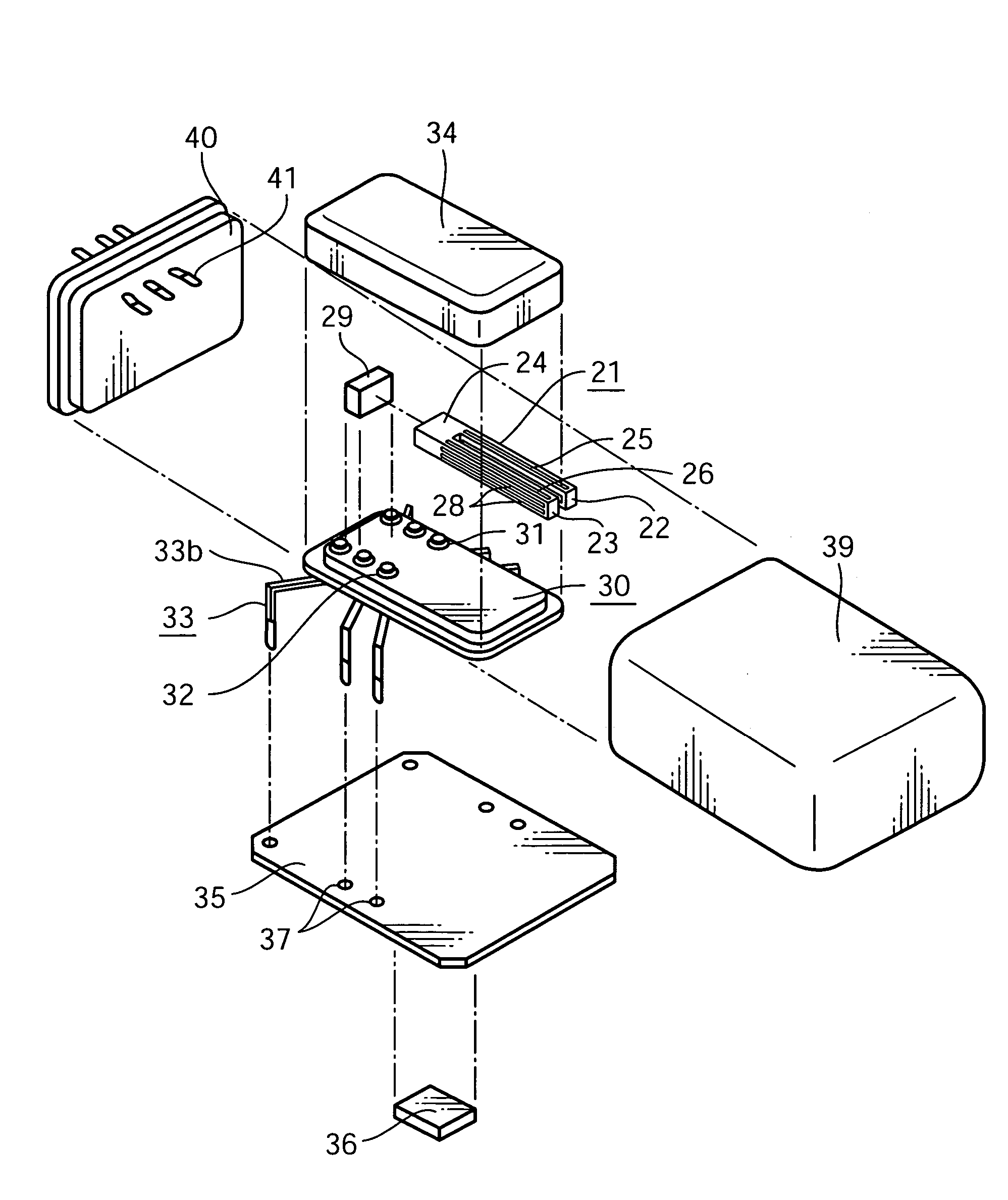
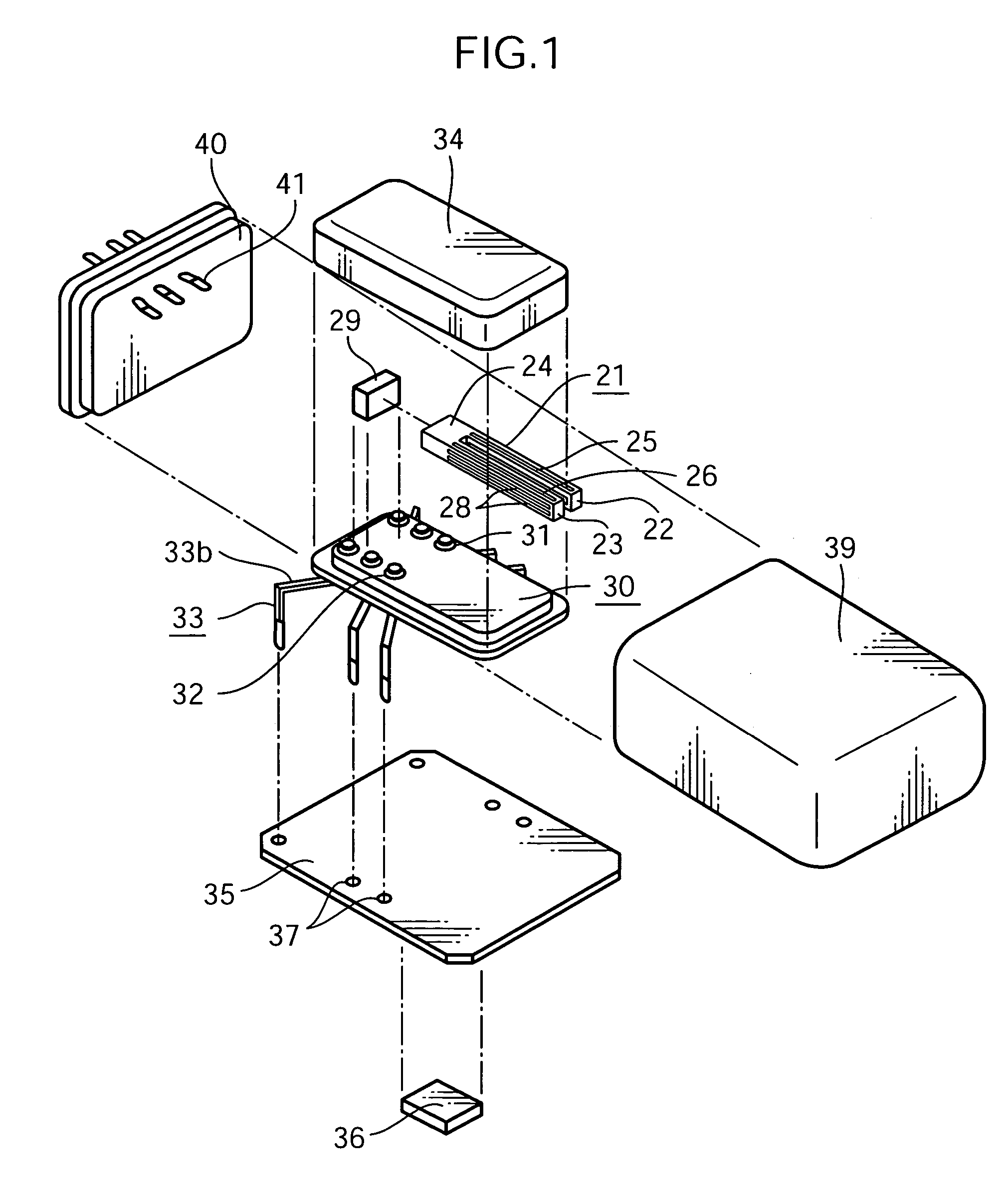
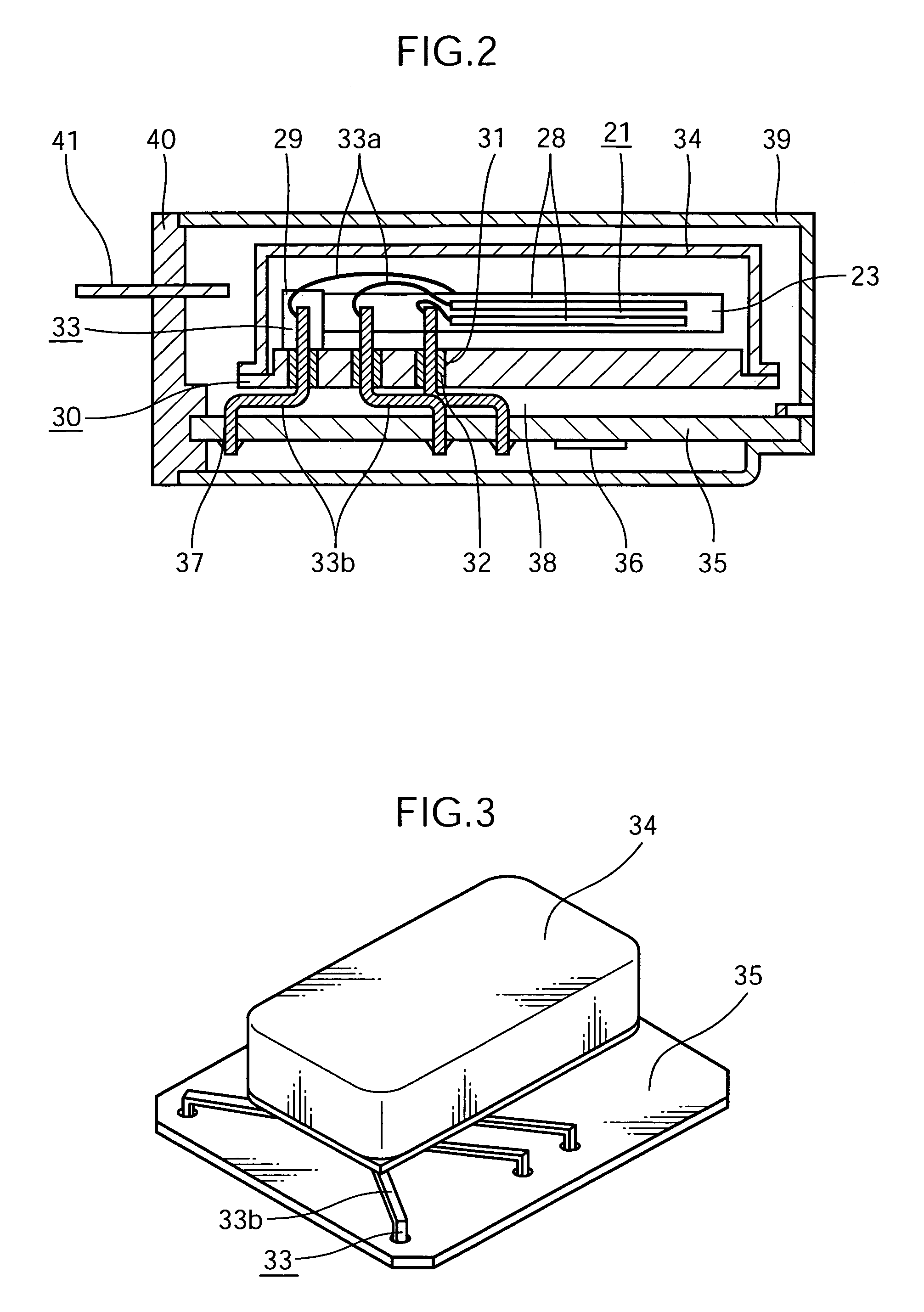
[0021]In the following, an angular velocity sensor in accordance with an embodiment of the invention is described referring to the drawings. FIG. 1 is an exploded perspective view of the angular velocity sensor in accordance with the embodiment of the invention. FIG. 2 is a cross-sectional side view of the angular velocity sensor. FIG. 3 is a perspective view showing a state in which a base block of the angular velocity sensor is fixed to a circuit board. FIG. 4 is a top plan view showing a state in which the base block of the angular velocity sensor is fixed to the circuit board.

[0022]The angular velocity sensor shown in FIGS. 1 through 4 includes a tuning fork unit 21 made of crystal. The tuning fork unit 21 is constituted of a quadrangular prismatic drive electrode vibrator 22, a quadrangular prismatic detection electrode vibrator 23 arranged parallel to the drive electrode vibrator 22, and a connecting portion 24 for integrally connecting an end of the drive electrode vibrator 2...


PUM


Abstract

An angular velocity sensor includes a tuning fork unit; a base block provided with a terminal for outputting an output signal from the tuning fork unit to the exterior; a cover for housing the tuning fork unit in a space defined by combination with the base block; a circuit board for fixing the terminal on the base block, the circuit board being provided with a processing circuit for processing the output signal from the tuning fork unit; and a casing for housing the base block, the cover, and the circuit board. The terminal on the base block is fixed to the circuit board, with a clearance being defined by the base block and the circuit board. The terminal on the base block in the clearance has a flexure portion, and the flexure portion absorbs a vibration of a high frequency applied from the exterior.

Description

BACKGROUND OF THE INVENTION[0001]1. Field of the Invention[0002]The present invention relates to an angular velocity sensor, and more particularly to an angular velocity sensor for use in posture control of a movable object such as an aircraft and an automotive vehicle, a navigation system or the like.[0003]2. Description of the Related Art[0004]A well-known angular velocity sensor has a construction as shown in FIG. 7. FIG. 7 is a cross-sectional side view of the conventional angular velocity sensor.[0005]The angular velocity sensor shown in FIG. 7 has a base block 1 on which a tuning fork portion (not shown) is firmly fixed and a plurality of terminals 2 are mounted, so that an output signal from the tuning fork portion is outputted to the exterior by way of the terminals 2. The tuning fork portion is housed in a space defined by the base block 1 and a cover 3.[0006]The terminals 2 on the base block 1 are fixed spaced apart from each other on a first circuit board 4 by soldering. ...

Claims


Application Information

Patent Timeline
Patent Type & Authority Patents(United States)
IPC IPC(8): G01C19/00G01C19/56G01C19/5628
CPCG01C19/5628H05K3/308H05K2201/10151H05K2201/10757H05K2201/10848
Inventor MITANI, TOMOHIRO
Owner PANASONIC CORP
Why Eureka
Try Eureka