Cutting insert

A technology of cutting inserts and inserts, applied in turning equipment, accessories of toolholders, tools for lathes, etc., can solve the problems of inability to achieve smooth chip processing, increased cutting resistance, chip blocking, etc., and achieve stable chip processing. , The effect of preventing the increase of cutting resistance and preventing chip clogging

Inactive Publication Date: 2008-10-01
MITSUBISHI MATERIALS CORP
View PDF4 Cites 22 Cited by
  • Summary
  • Abstract
  • Description
  • Claims
  • Application Information

AI Technical Summary

Problems solved by technology

[0005] Therefore, chips are pushed into the concave portion of the outer wall surface to cause chip clogging, and smooth chip disposal cannot be achieved, which may lead to an increase in cutting resistance, etc.

Method used


Image

  • Cutting insert
  • Cutting insert
  • Cutting insert

Examples


Embodiment Construction

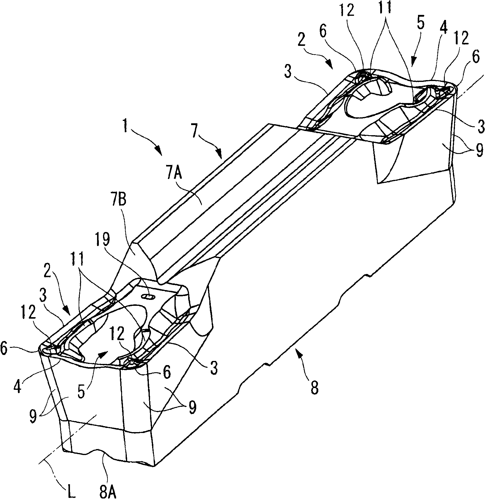
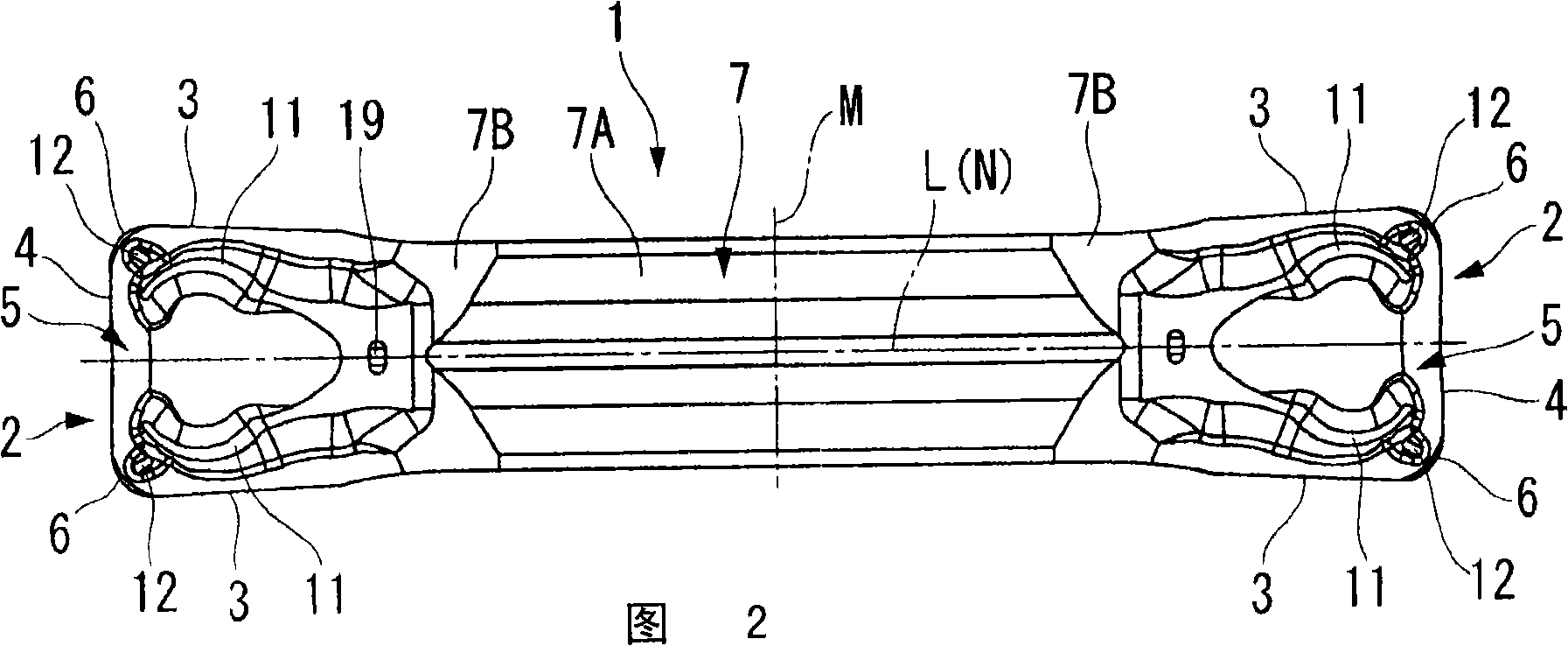
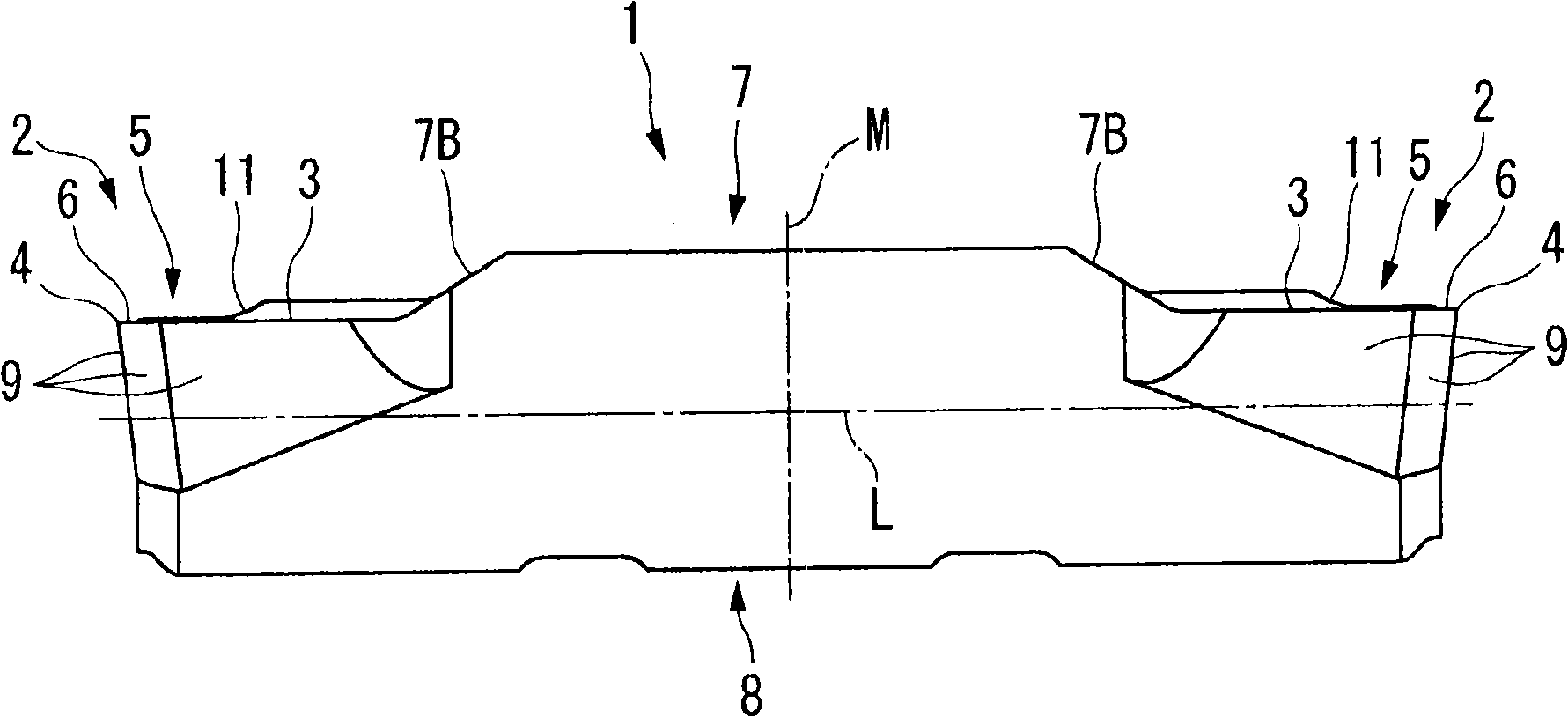
[0073] figure 1 7 to 7 are diagrams showing a first embodiment of the cutting insert of the present invention. In the present embodiment, the insert body 1 is formed of a hard material such as cemented carbide, and has a substantially square shaft shape (square column shape) extending along the axis L. As shown in FIG. The blade body 1 is formed approximately symmetrically with respect to a plane M which is perpendicular to the axis L and which is located in the length direction of the blade body 1 (direction of the axis L, FIGS. Figure 4 in the left and right directions) in the center. Furthermore, the blade main body 1 is also a symmetrical shape with respect to a plane N which is perpendicular to the plane M and which is located in the width direction of the blade main body 1 (Fig. 2 and Figure 4 in the up and down direction, in Figure 5 Middle is the left-right direction) center, including the axis L and in the thickness direction of the blade main body 1 ( image 3...


PUM


Abstract

A cutting insert has an insert body having a shaft-shape, wherein a cutting edge portion having a square rake face is formed on an end portion of the insert body, and wherein the rake face includes; a pair of side cutting edges extending in a longitudinal direction of the insert body; a front cutting edge extending in a transverse direction perpendicular to the longitudinal direction between each front ends of the side cutting edges; and a pair of protruded streaks extending toward a corner portion at which each of the side cutting edges intersects the front cutting edge, each of the protruded streaks including an outer wall face having a protruded curved face which faces the adjacent side cutting edge and protrudes toward the side cutting edge as seen in a direction facing the rake face and perpendicular to the longitudinal direction.

Description

technical field [0001] The present invention relates to a cutting insert used for grooving or cutting off a material to be cut in turning. This application claims against Japanese Invention Patent Application No. 2007-091952 and No. 2007-094884 filed on March 30, 2007, and Japanese Invention Patent Application No. 2008-012975 filed on January 23, 2008 Priority, its content is introduced here. Background technique [0002] As such a cutting insert used in grooving or parting, for example, Japanese Unexamined Patent Publication No. 9-174308 proposes a cutting insert having a pair of convex blades extending substantially in the longitudinal direction on the top surface of the cutting head. strips, the chip breaker pockets between these ribs, the crease lines extending between the pocket portions at the front and rear locations of the chip breaker pockets, and A pair of protrusions (bulges) between the blades use the area near the junction of the crease line and the protrusion...

Claims


Application Information

Patent Timeline
Patent Type & Authority Applications(China)
IPC IPC(8): B23B27/04B23B27/16
Inventor 长屋秀彦麻生典夫今井康晴
Owner MITSUBISHI MATERIALS CORP
Why Eureka
Try Eureka