Vacuum drainage system

A sewage system and vacuum drainage technology, which is applied in the field of fluid collection and transportation technology and system, can solve the problems of large excavation engineering, high construction cost, and long construction period, and achieve the reduction of construction cost, elimination of pollution, and energy consumption of operation The effect of reduced spending

Inactive Publication Date: 2008-10-01
SHANGHAI DONGYA UNITED BUILDING INDAL GROUP +3
View PDF0 Cites 14 Cited by
  • Summary
  • Abstract
  • Description
  • Claims
  • Application Information

AI Technical Summary

Problems solved by technology

The gravity transportation method has many disadvantages such as leakage, leakage pollution, discharge pollution, blockage and overflow, and high maintenance cost. It requires the construction of gravity lifting pump stations, large excavation works, and laying of large-scale pipeline networks. The construction cost is high and the construction period is long. question

Method used


Image

  • Vacuum drainage system
  • Vacuum drainage system
  • Vacuum drainage system

Examples


Embodiment Construction

[0024] In order to make the technical means, creative features, goals and effects achieved by the present invention easy to understand, the present invention will be further described below in conjunction with specific embodiments.

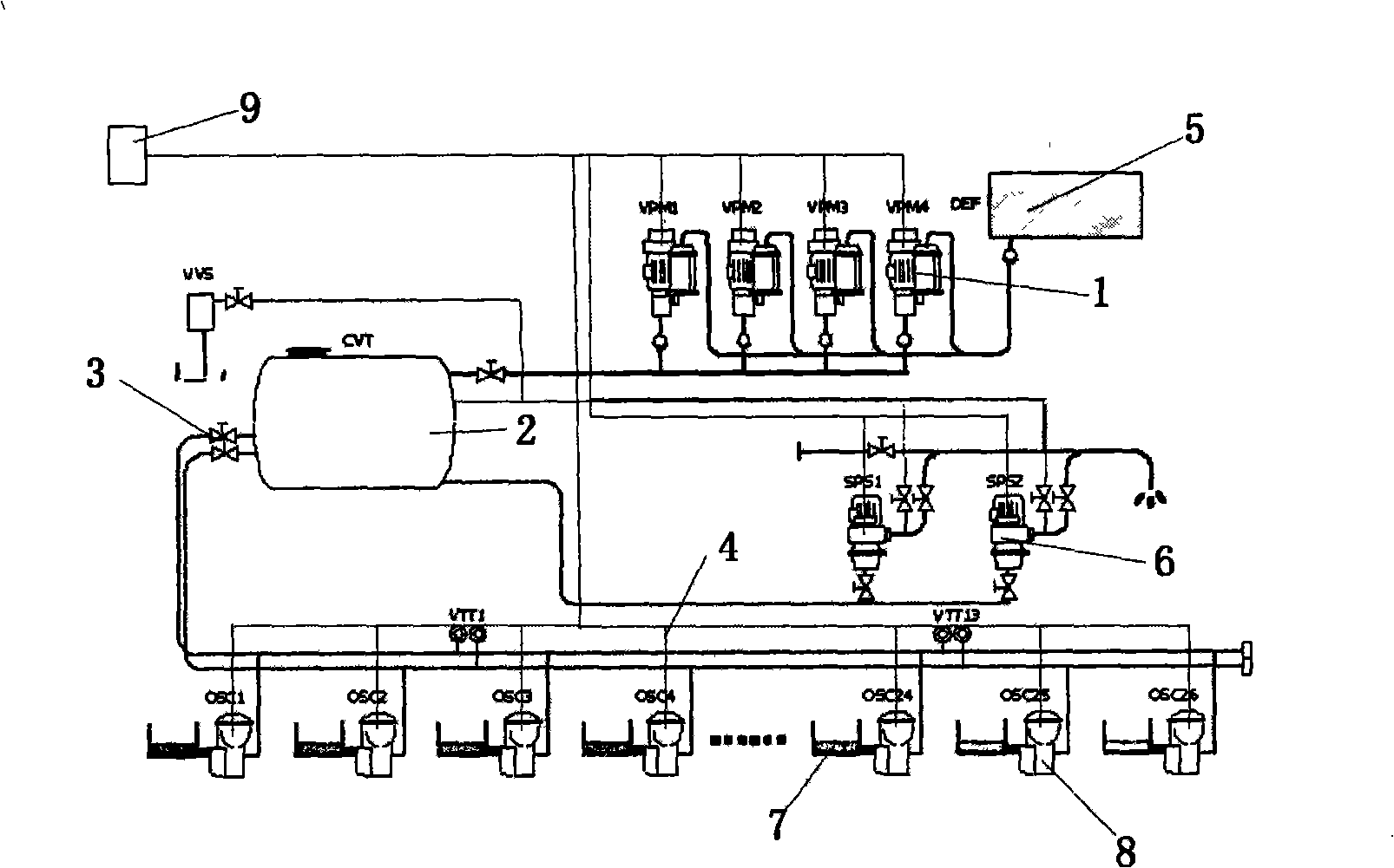
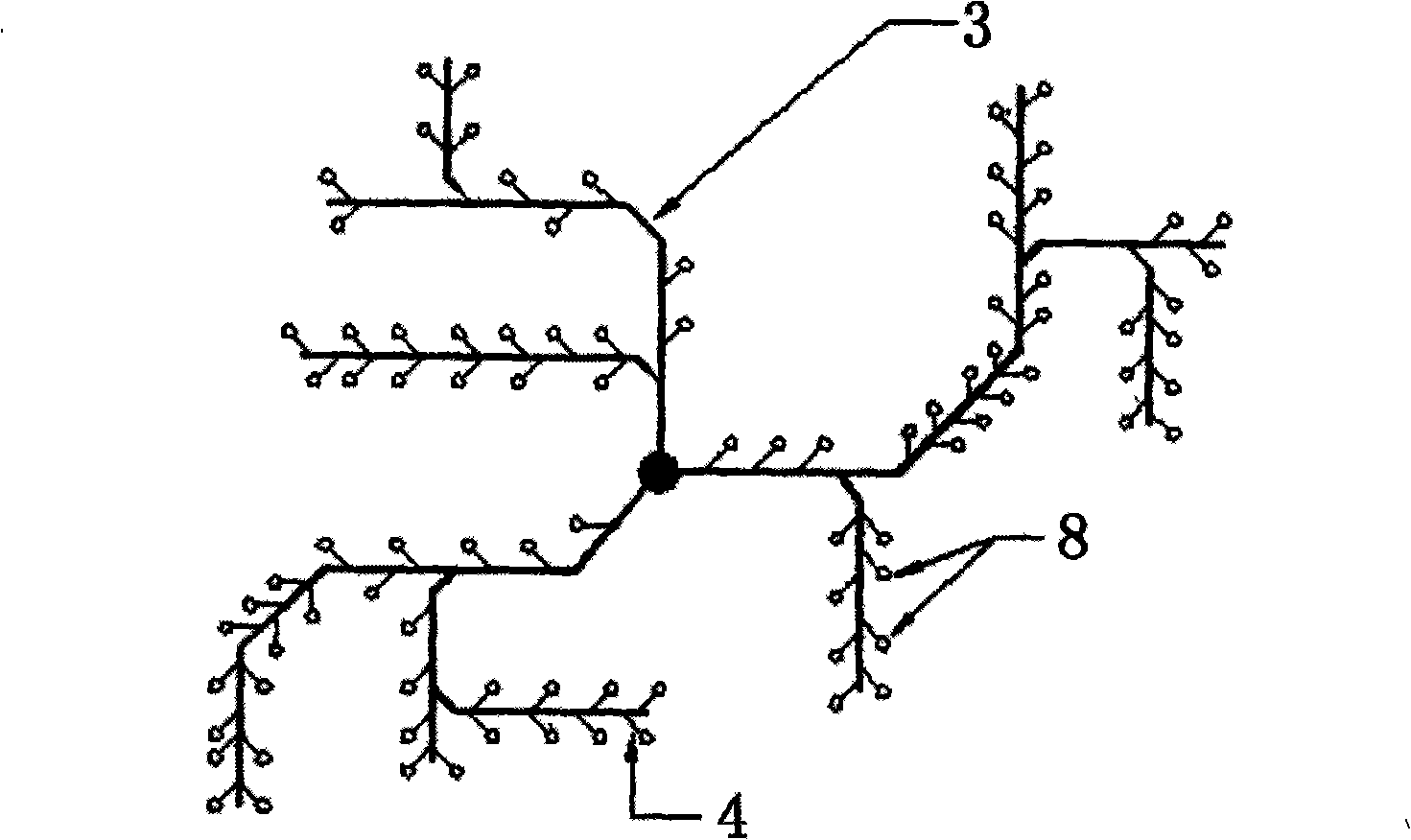
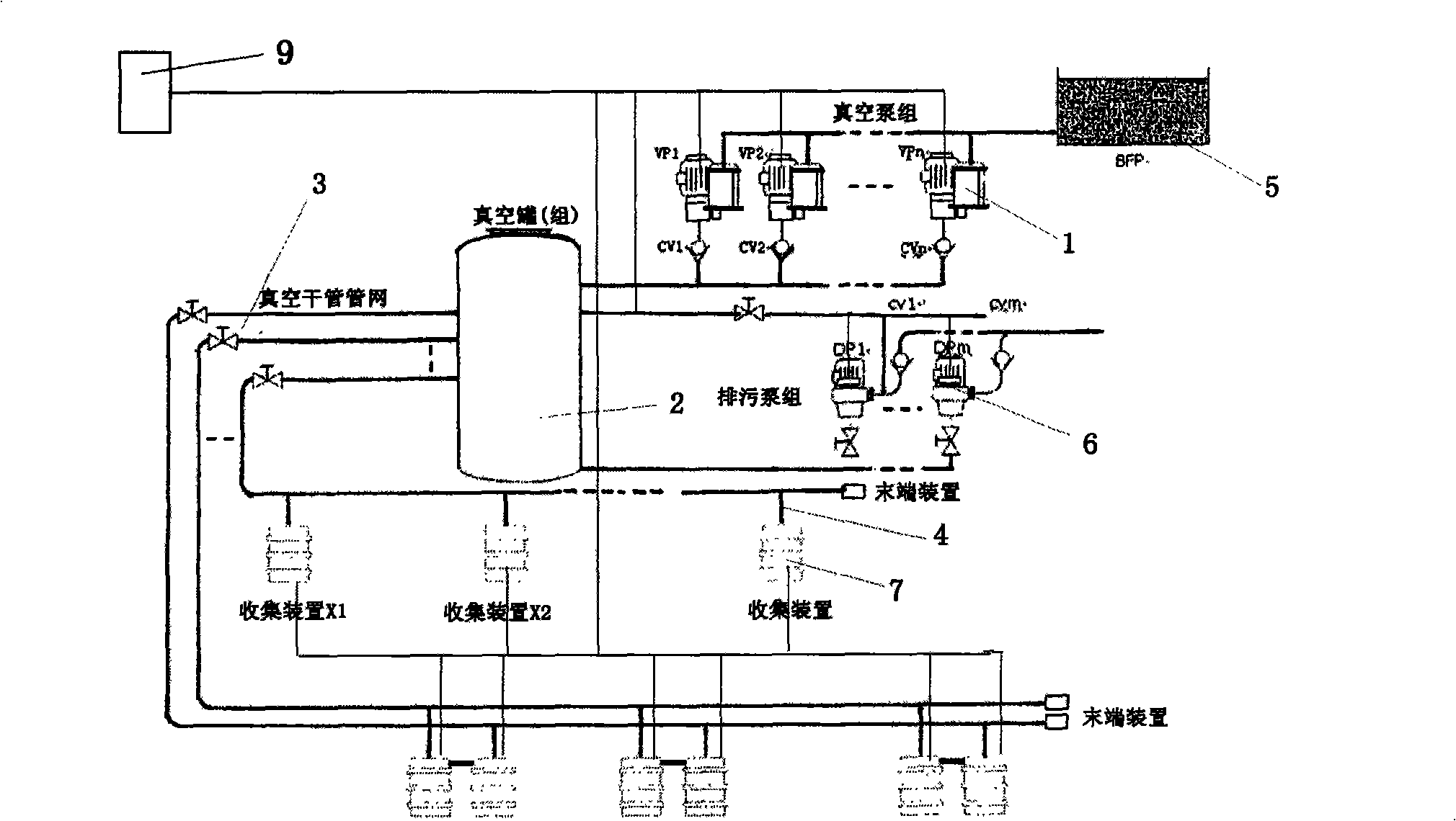
[0025] Such as figure 1 The vacuum drainage and sewage system shown includes a vacuum pump group 1, a vacuum tank 2, a vacuum main pipeline 3, a vacuum branch pipeline 4, a biological filter tank 5, a sewage pump group 6, several collection devices 7, several vacuum boundary valves 8, and a control device 9 composition; biological filter 5, vacuum pump group 1, sewage pump group 6 and vacuum tank 2 constitute a vacuum power station, which can be concentrated in one building unit, and the air inlet of vacuum pump group 1 is connected to the vacuum tank 2 through pipelines and shut-off valves connection, responsible for maintaining the vacuum degree of the vacuum tank 2 and its connected vacuum pipe network; the inlet of the sewage pump group 6 is c...


PUM


Abstract

A vacuum drainage system includes a vacuum pump group, a vacuum can, a vacuum trunk conduit, vacuum branch conduits, a biological filter, a dredge pump group, a plurality of collecting devices, a plurality of vacuum demarcation valves, and a control device. The biological filter, the vacuum pump group, the dredge pump group and the vacuum can constitute a vacuum power station, the intake port of the vacuum pump group is connected with the vacuum can through conduits as well as a stop valve; the aspirating pipe of the dredge pump group is connected with the vacuum can through conduits, and the discharging tube is connected with the water quality treatment plant or higher level pipe network; the vacuum trunk conduit is connected with the vacuum can and extends to the user site collecting device from the place, the plurality of collecting devices are distributed at each user site, which are connected to the vacuum trunk conduit through the vacuum branch conduits; the vacuum demarcation valves are mounted on the vacuum branch conduits; the control device is connected with liquid level detectors in the vacuum pump group, the dredge pump group as well as the collecting devices; pressure testing sensors in the vacuum demarcation valve and the vacuum can; and the like.

Description

technical field [0001] The present invention relates to a fluid collection and conveying technology and system, in particular to a vacuum drainage and sewage discharge system for vacuum energy storage drainage and sewage discharge technology and system. The system is used to store sewage from vacuum sewage pipes and then transport the sewage to sewage treatment plants or similar. Background technique [0002] At present, there are three ways of collecting and transporting rainwater, waste water and sewage in developed countries in the world, gravity, vacuum and pressure. China currently collects and transports rainwater, waste water, and sewage only by traditional gravity. The gravity transportation method has many disadvantages such as leakage, leakage pollution, discharge pollution, blockage and overflow, and high maintenance cost. It requires the construction of gravity lifting pump stations, large excavation works, and laying of large-scale pipeline networks. The constr...

Claims


Application Information

Patent Timeline
Patent Type & Authority Applications(China)
IPC IPC(8): E03F1/00
Inventor 章伟康
Owner SHANGHAI DONGYA UNITED BUILDING INDAL GROUP
Why Eureka
Try Eureka