Light emitting apparatus

A light-emitting device and light source technology, which is applied in signal devices, lighting devices, electroluminescence light sources, etc., can solve the problems of reducing the output voltage of switching regulators and not being able to detect grounding, etc.

Inactive Publication Date: 2008-10-01
KOITO MFG CO LTD
View PDF1 Cites 5 Cited by
  • Summary
  • Abstract
  • Description
  • Claims
  • Application Information

AI Technical Summary

Problems solved by technology

[0007] In the conventional technology described above, when the output terminal of the switching regulator is grounded, it is assumed that an abnormality occurs at the output terminal of the switching regulator.
[0008] That is, in the conventional technology, the whole LED block is used as the load of the switching regulator, and when the whole LED block is abnormal, the output voltage of the switching regulator is lowered, so even if any part of the LEDs is grounded, nor is it possible to detect the ground

Method used


Image

  • Light emitting apparatus
  • Light emitting apparatus
  • Light emitting apparatus

Examples


Embodiment Construction

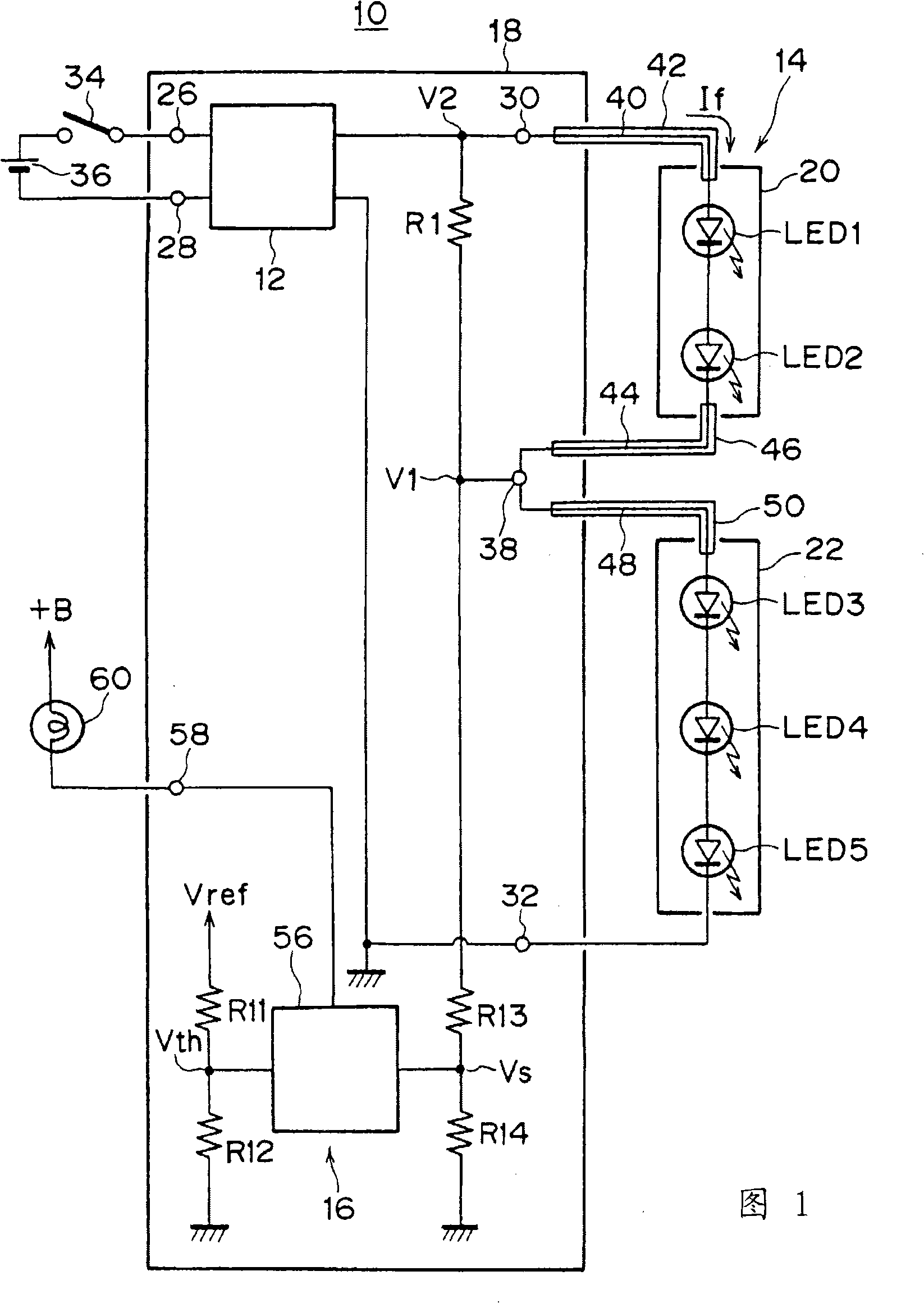
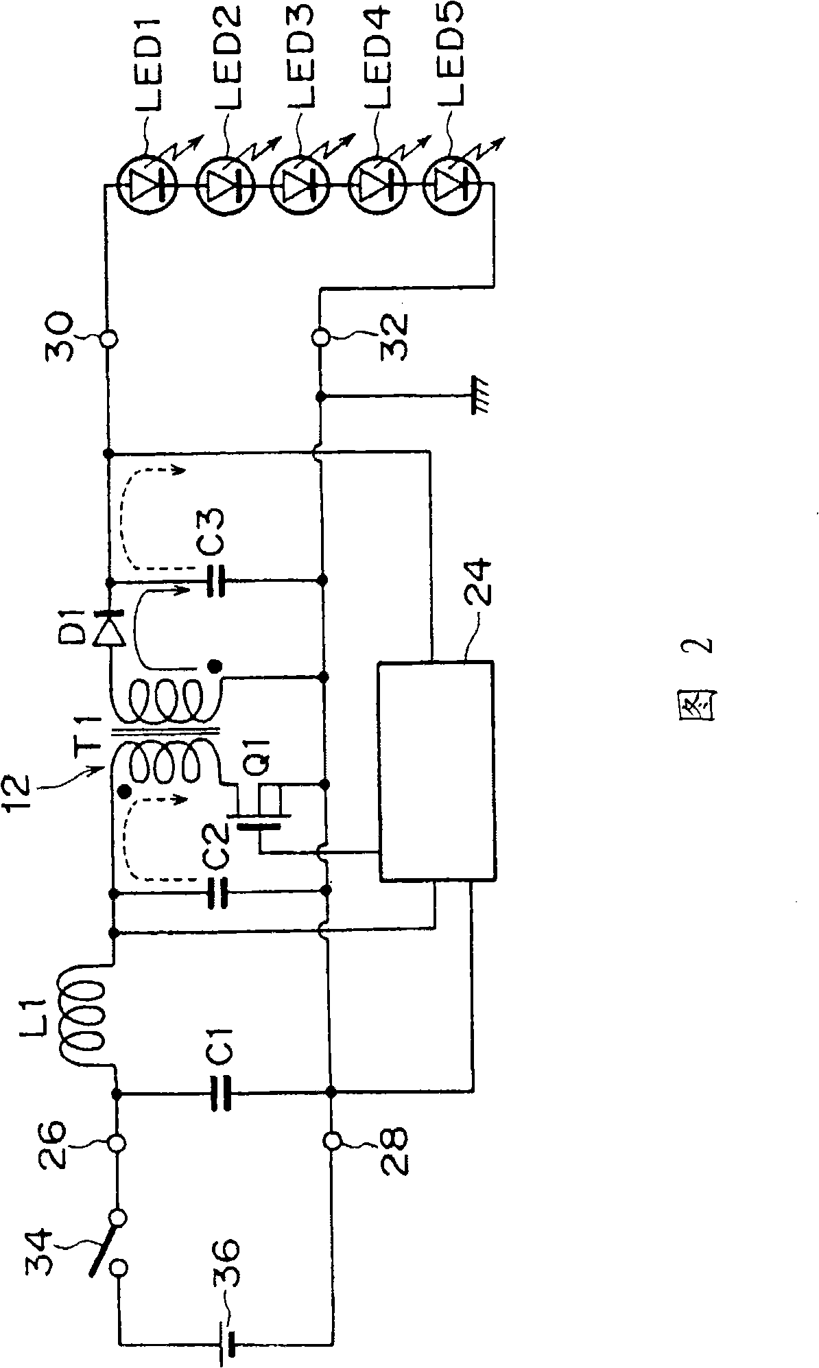
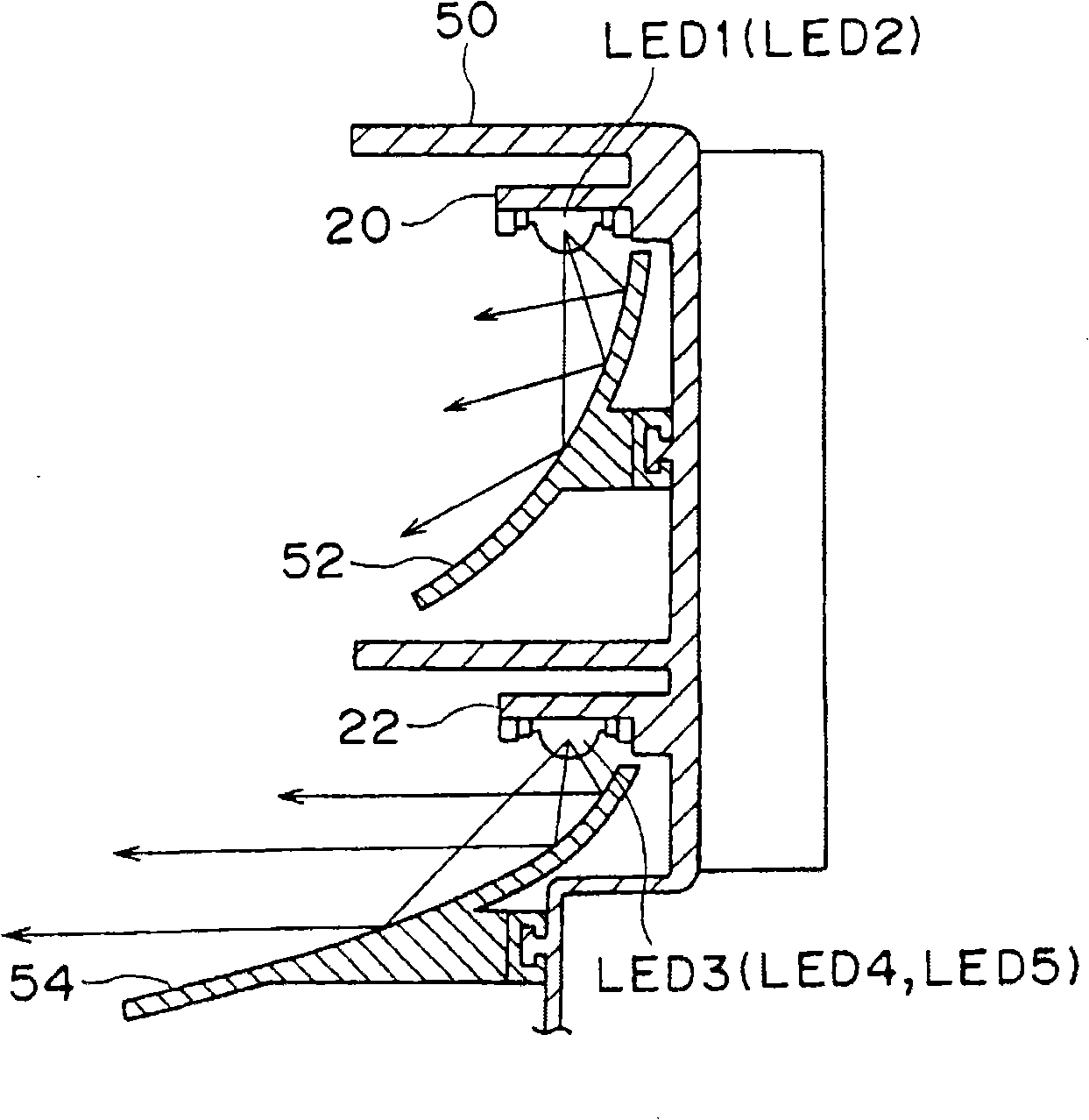
[0034] Hereinafter, an embodiment of the present invention will be described with reference to the drawings. Fig. 1 is a block diagram showing a light emitting device according to an embodiment of the present invention, and Fig. 2 is a circuit diagram of a DC / DC converter, image 3 It is a cross-sectional view when an LED is mounted on a body part formed on a bracket, Figure 4 It is a waveform diagram illustrating the state of voltage and current in an output terminal and a connection point. FIG. 5 is a block diagram showing a light-emitting device according to a second embodiment of the present invention. FIG. 6 is a block diagram showing a light-emitting device according to a third embodiment of the present invention. structure diagram.

[0035] In FIG. 1 , a light emitting device 10 includes a DC / DC converter 12 , a resistor R1 , a light source block 14 , and a ground detection circuit 16 . The DC / DC converter 12 , the resistor R1 and the ground detection circuit 16 are m...


PUM


Abstract

The invention relates to a light emitting apparatus for detecting grounding of a plurality of detecting object positions in the positions connected on each electrode of a plurality of semiconductor light sources. In LED (1) to LED (5) which are arranged between output terminals (30, 32) of a DC / DC convertor (12), a resistance (R1) is connected with two terminals of LED (1) and LED (2) as detecting objects, and two terminals of the resistance (R1) are as the detecting object positions connecting anode of LED (1) and cathode of LED (2), and one terminal of the resistance (R1) is connected with a grounding detecting circuit (16) via a connecting point (38). Because when connecting to the two terminals of the resistance (R1), and connecting the output terminal (30) or the detecting object position of the connecting point grounding, a voltage (V1) of the connecting point is reduced to grounding potential, the invention can detect the grounding of the detecting object positions connecting the output terminals (30) or the connecting point via using the grounding detecting circuit (16) to detect a change of the voltage.

Description

technical field [0001] The present invention relates to a light-emitting device, in particular to a light-emitting device comprising a light source for a vehicle lamp with a semiconductor light-emitting element and having a lighting circuit for lighting the semiconductor light-emitting element. Background technique [0002] Conventionally, it is known that semiconductor light-emitting elements such as LEDs (Light Emitting Diode) are used as light sources for vehicle lamps, and lighting control circuits for controlling lighting of LEDs are incorporated in such vehicle lamps. [0003] As the lighting control circuit, a switching regulator capable of controlling the output voltage to the LED based on the current of the LED is used. Even if a plurality of LEDs are connected in series or in parallel to the switching regulator, the switching regulator can control the output voltage so that the current flowing through each LED becomes a predetermined current. [0004] However, if ...

Claims


Application Information

Patent Timeline
Patent Type & Authority Applications(China)
IPC IPC(8): F21S8/10F21S4/00F21V23/00H05B37/03F21W101/02F21Y101/02F21W107/10
CPCH05B33/0884B60Q11/00H05B33/0803H05B33/0815H05B45/385H05B45/54
Inventor 矶部晃一野寄靖史盐津文规
Owner KOITO MFG CO LTD
Why Eureka
Try Eureka