

Method and apparatus for drying film and solution casting method
A drying film and drying technology, applied in lighting and heating equipment, progressive dryers, drying gas arrangement, etc., can solve problems such as weak cleaning effect
Active Publication Date: 2008-10-01
FUJIFILM CORP
View PDF2 Cites 2 Cited by
- Summary
- Abstract
- Description
- Claims
- Application Information
AI Technical Summary
Problems solved by technology
Method used
View moreImage
Smart ImageViewing Examples

Examples
Embodiment 1
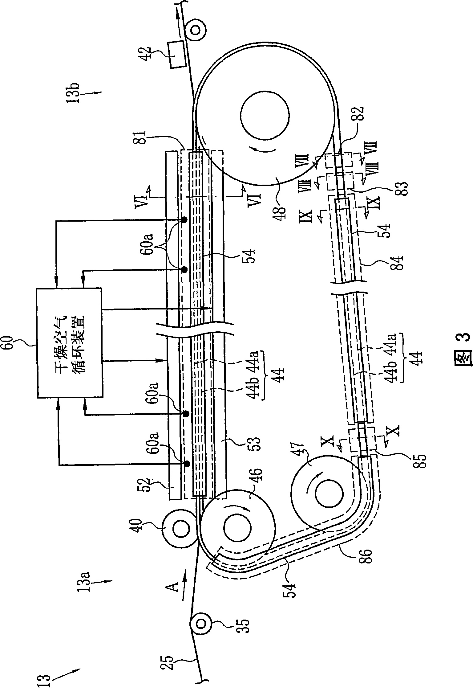
[0141] In the air-jet cleaning zone 83, nitrogen gas is blown onto the pins 72, the needle plate 73, the carrier body 74, the rails 44a and 44b, and the guide rollers 76 to 79 (hereinafter referred to as air-jet cleaning).
Embodiment 2
[0143] In addition to air jet cleaning, steam is blown onto the pins 72, the needle plate 73, the rails 44a and 44b, the carrier body 74, and the guide rollers 76 to 79 through the nozzles 120a to 120c in the steam cleaning zone 82 (hereinafter referred to as steam cleaning) .
Embodiment 3
[0145] In addition to jet cleaning and steam cleaning, nitrogen gas is purged from the track covers 54 and 55 (hereinafter referred to as gas purging).
Login to View More PUM
| Property | Measurement | Unit |
|---|---|---|
| thickness | aaaaa | aaaaa |
| diameter | aaaaa | aaaaa |
| viscosity | aaaaa | aaaaa |
Abstract
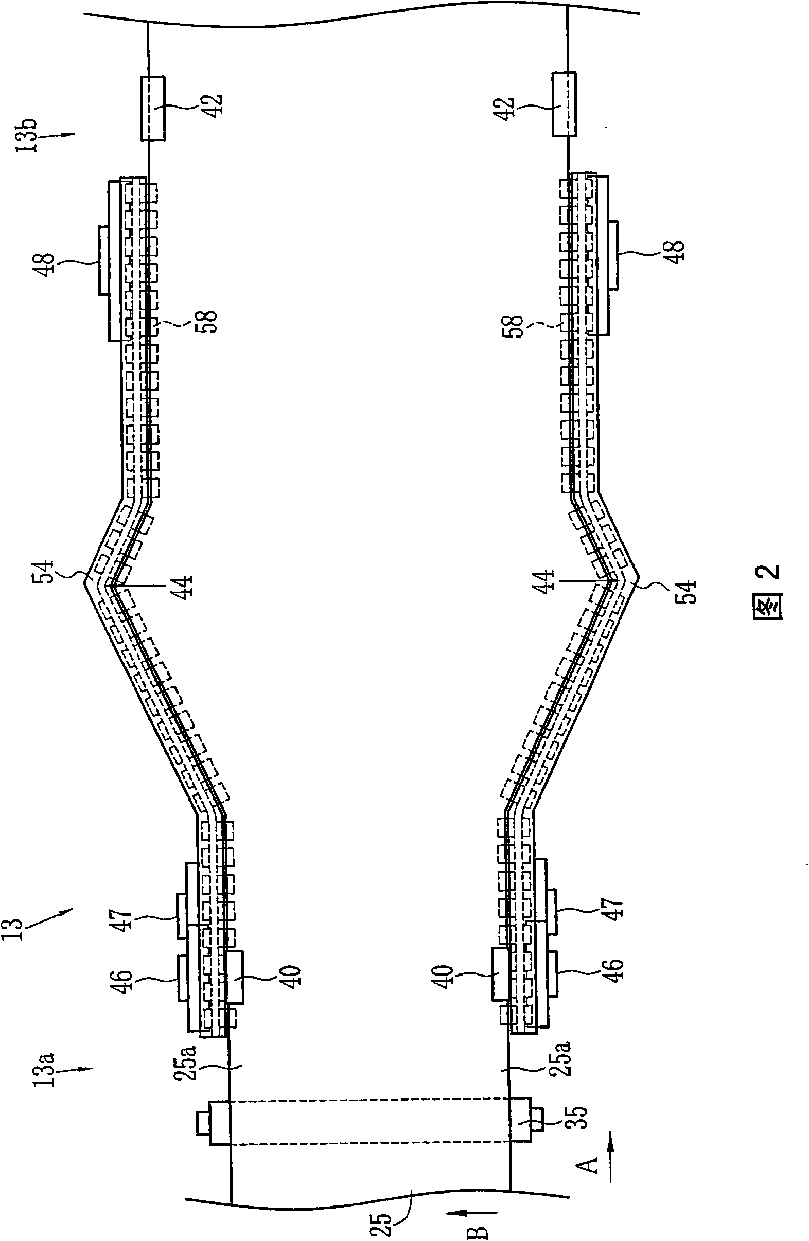
In a pin tenter, a wet film is conveyed and dried in a state that edges of the wet film are pierced by pins. The plurality of pins are fixed to a pin plate. The pin plate is supported by a pin carrier. The pin carrier is disposed between rails. Movement of the pin carrier is guided by the rails. In a steam cleaning area, foreign substances adhered to the pins, the pin plates, and the pin carriers are removed by blowing steam. In a jet gas cleaning area, residual foreign substances and residual water content after the steam cleaning are blown off and removed by blowing nitrogen gas.
Description
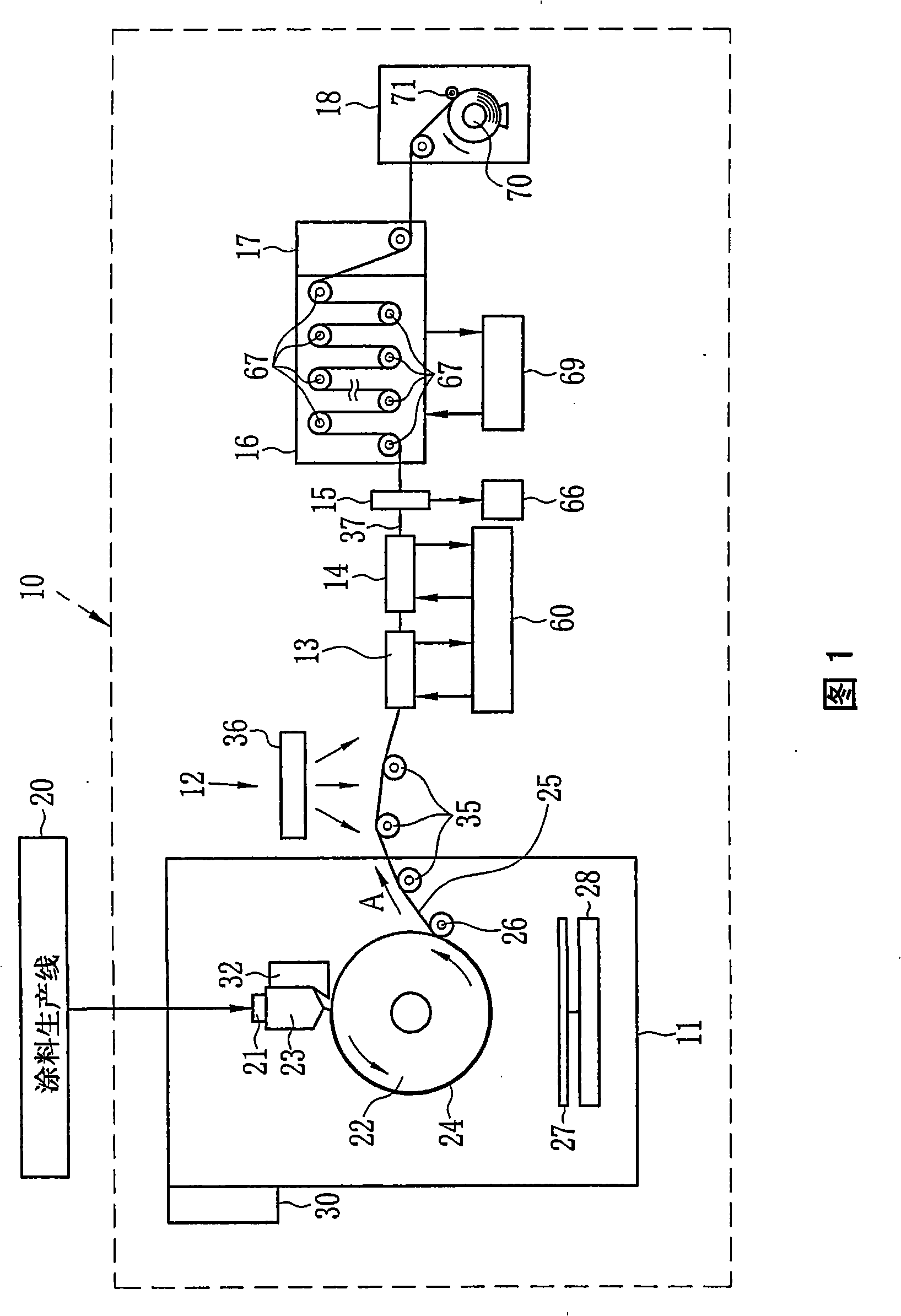
technical field [0001] The present invention relates to a method and apparatus for drying a film while conveying the film in a state where both side portions of the film are fixed, and to a solution casting method incorporating the method and apparatus for drying the film. Background technique [0002] The polymer film has excellent optical clarity and flexibility, and is formed into a thin and lightweight film. Accordingly, the polymer film is used as an optical functional film for various applications. In particular, cellulose ester films prepared from cellulose acylate and the like have strength and low birefringence in addition to the above properties. Cellulose ester films are used as protective films for polarizing filters and optical compensation films constituting liquid crystal displays (LCDs), the market of which is expanding, and photosensitive films. [0003] The solution casting method is one of the production methods for polymer films. According to the solut...
Claims
Login to View More Application Information
Patent Timeline
 Patent Type & Authority Applications(China)
IPC IPC(8): F26B13/10B29C41/24B29C71/02B29L7/00
CPCF26B13/12B29B13/06F26B21/14
Inventor 中村敏和加藤盛孝
Owner FUJIFILM CORP