Device for suspending a unit such that vibrations are damped and complete equipment

一种成套设备、套环的技术,应用在机械设备、非旋转振动抑制、薄板连接等方向,能够解决少有自由空间、困难延长、增加成套设备安装过程等问题,达到缩短安装过程、简化安装过程的效果

Inactive Publication Date: 2011-08-03
ROBERT BOSCH GMBH
View PDF1 Cites 1 Cited by
  • Summary
  • Abstract
  • Description
  • Claims
  • Application Information

AI Technical Summary

Problems solved by technology

However, there is generally little free space on the car for such tightening tools
In addition, the use of a complete set of tightening tools at the manufacturer also increases the difficulty and prolongs the installation process of the complete set of equipment

Method used


Image

  • Device for suspending a unit such that vibrations are damped and complete equipment
  • Device for suspending a unit such that vibrations are damped and complete equipment
  • Device for suspending a unit such that vibrations are damped and complete equipment

Examples


Embodiment Construction

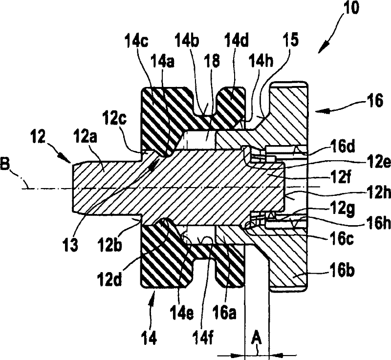
[0011] exist figure 1 The device 10 shown in is constituted by a pull rod 12 , an elastomer piece 14 supported by the pull rod, and a clamp 16 partially projecting into the interior of the elastomer piece 14 . The gripper 16 is guided on the draw rod 12 in an axially displaceable manner and can be transferred from the basic position to the clamping position by manual operation.

[0012] The tie rod 12 is a cylindrical metal piece, preferably made of solid material, with a multiple stepped profile. exist figure 1 The longitudinal axis of the tie rod 12 and the longitudinal axis of the entire device 10 are denoted by B. The first tie rod section 12a with a reduced outer diameter serves to secure the tie rod at the figure 1 in the accommodating hole of the kit not shown. This first section 12a can have a smooth or knurled surface on the circumferential side when it is provided that the tie rod is anchored in the receiving hole by means of a press-in method. If it is provided...


PUM


Abstract

The invention relates to a device (10) for suspending a unit (22), especially a hydraulic unit of an electronically slip-controlled brake system of a motor vehicle, in a receptacle (32a, b, c) provided for that purpose on the vehicle such that vibrations are damped. Hydraulic units of vehicle brake systems are usually equipped with an electric motor (26) which drives pumps located in the hydraulic unit. The brake pressure in the wheel brakes can be modulated via said pumps. The pump drive can cause mechanical and hydraulic vibrations in the unit (22) which can result in unwanted operational noise in case said vibrations are transmitted to the vehicle body without being damped. Devices (10) known in prior art for damping such vibrations can be preloaded with the aid of tools.; Disclosed isa manually preloaded device (10) because generally space for using tools is limited in the vehicle. The inventive device (10) comprises a clamping means (16) which is guided in an axially movable manner on an armature (12) that is fixed to the hydraulic unit and which can be moved from a basic position into a clamping position. The clamping means (16) is interlocked with the armature (12) in bothpositions.

Description

technical field [0001] The invention relates to a device for suspending a plant in a vibration-damped manner in a receptacle provided for this purpose. Background technique [0002] A device of this type has been disclosed, for example, in DE 100 36 575 A1. The disclosed device has a cylindrical tie rod fastened to the assembly. The pull rod partially exceeds the overall dimensions of the complete equipment. Arranged on this projecting section of the tie rod is an elastomer piece, which has an intermediate section with a reduced outer diameter and two larger outer diameters arranged on both sides of the intermediate section. end section. The elastomer part bears against the outer wall of the unit with its end face and cooperates with the flange of the support sleeve at its opposite end. The support sleeve is acted upon by a nut screwed onto the threaded section of the outer end of the anchor column. By tightening the nut, the elastomer part is axially clamped, which pro...

Claims


Application Information

Patent Timeline
Patent Type & Authority Patents(China)
IPC IPC(8): F16F15/08B60T8/36F16B5/06F16B21/07F16B21/04
CPCB60T8/3685F16B35/04F16F15/08F16F1/3732F16B21/073B60T8/36F16B21/04F16B21/07
Inventor M·施利特兹库斯A·韦M·梅尔
Owner ROBERT BOSCH GMBH
Why Eureka
Try Eureka