
Demountable handle for cooking utensils

A technology for handles and cooking utensils, which is applied to household appliances, kitchen utensils, applications, etc., can solve the problems of poor connection firmness, no disassembly structure, inconvenient use, etc., and achieves the effect of simple structure, easy operation and firm connection

Active Publication Date: 2008-10-08
ZHEJIANG SUPOR CO LTD
View PDF1 Cites 16 Cited by
  • Summary
  • Abstract
  • Description
  • Claims
  • Application Information

AI Technical Summary

Problems solved by technology

The container with a detachable handle is only connected through a groove and a joint, and the connection is not firm enough. Secondly, there is no corresponding disassembly structure, which makes the operation troublesome and inconvenient to use during disassembly.

Method used


Image

  • Demountable handle for cooking utensils
  • Demountable handle for cooking utensils
  • Demountable handle for cooking utensils

Examples


Embodiment 2

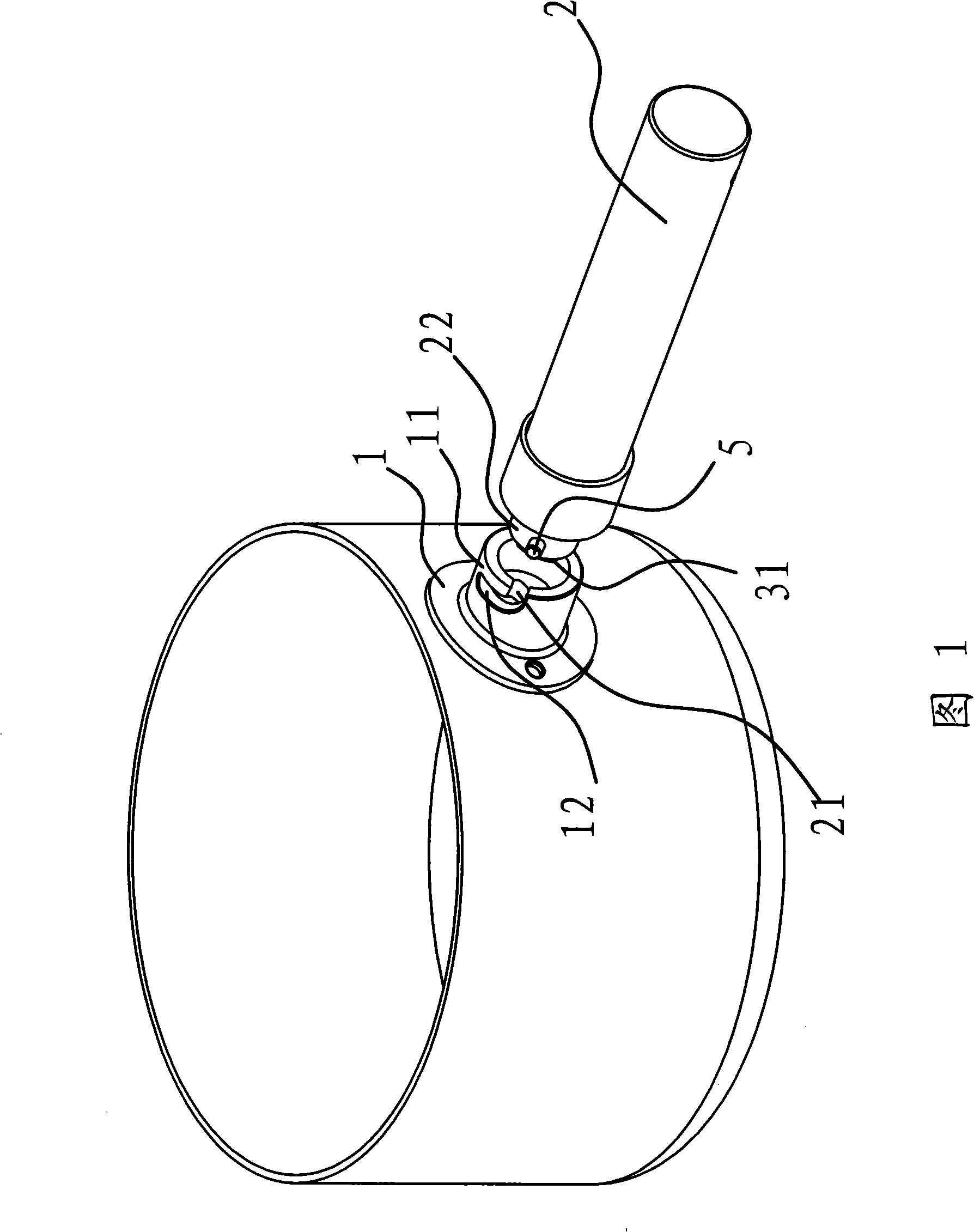
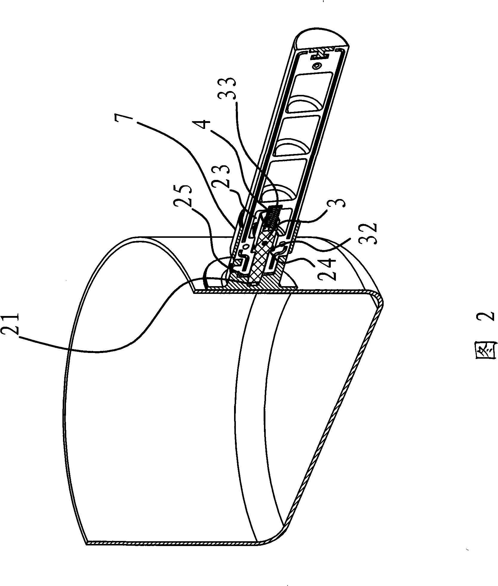
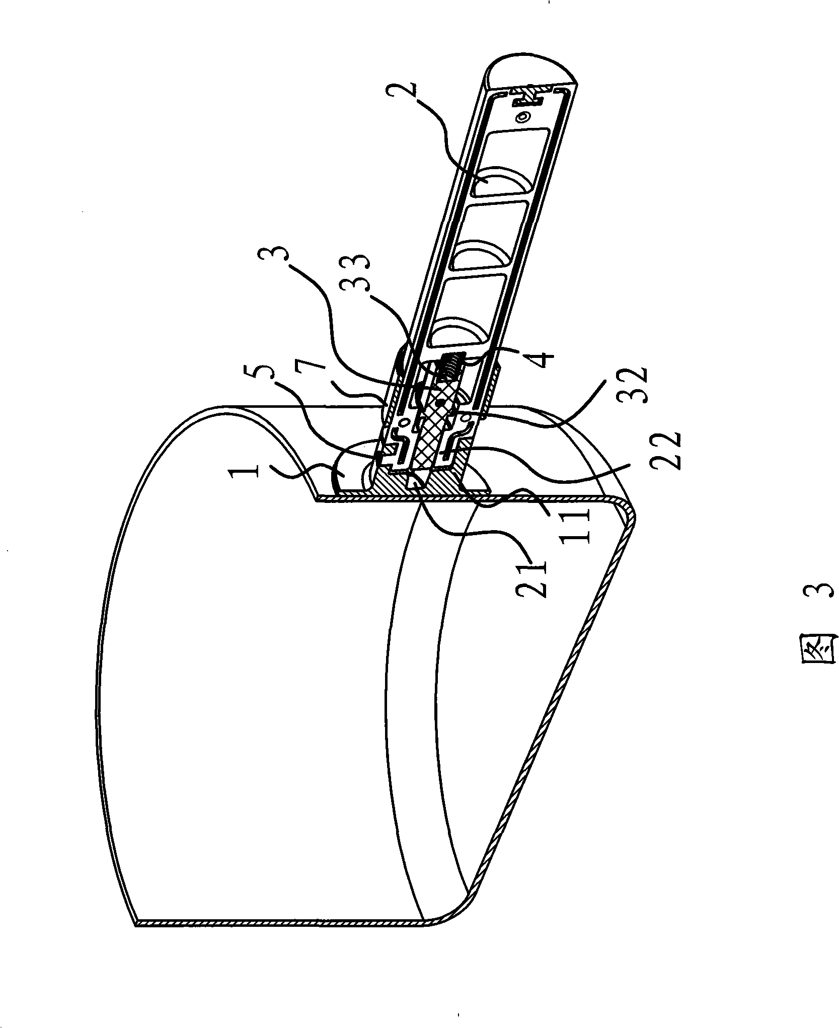
[0033] The content of embodiment 2 is basically the same as that of embodiment 1, the difference is that the snap-fit ​​mechanism includes an internal thread arranged in the joint 11 of the handle base 1 and an internal thread arranged outside the tenon 22 of the handle body 2 and on the handle base 1 Internal thread to match external thread. Through this structure, the handle body 2 and the handle base 1 can be axially fixed.

Embodiment 3

[0035] The content of embodiment 3 is basically the same as that of embodiment 1, the difference is that the end of the handle body 2 is sleeved in the handle seat 1, the above-mentioned limiting member 3 is set away from the axis line of the handle body 2, and When the handle body 2 drives the limiting member 3 to rotate, the outer end 31 of the limiting member 3 can enter the groove 21 provided on the handle base 1 . Since the end of the handle body 2 is sleeved in the handle seat 1, the rotation of the handle body 2 is centered on the axis line of the handle body 2, and the limiter 3 deviates from the axis line of the handle body 2. After the positioning member 3 is inserted into the groove 21, the limiting member 3 will make the handle body 2 unable to rotate any more, so as to achieve circumferential positioning.


PUM


Abstract

The invention provides a detachable cooker handle, pertaining to the technical field of living article, which solves the problems of the prior cooker handle, such as poor connection, troublesome disassembly and inconvenient use. The detachable cooker handle includes a strip-type handle body and a handle base arranged at one end of the handle body. The handle body is internally provided with a strip-type stopper and a spring along the axial lead direction of the handle body; the external end of the stopper extends out of the end face of the handle body under the spring effect; the handle base is provided with a groove matched with the external end of the stopper; the handle body is sheathed on the handle base; a clamping mechanism is also arranged between the handle body and the handle base which can form the axial positioning of the handle body and the handle base after the handle body rotates; in addition, after the handle body and the handle base are axially positioned, the stopper is inserted into the groove to form a circumferential positioning. The detachable cooker handle provided by the invention with a circumferential or axial positioning mechanism has the advantages of simple structure, quick and stable connection and convenient use.

Description

technical field [0001] The invention belongs to the technical field of daily necessities, and relates to a cooker handle, in particular to a detachable cooker handle. Background technique [0002] Along with the raising of living standard, the cooking utensils that people use in the kitchen is constantly increasing, and these cooking utensils can take up a large amount of kitchen space, and in order to save the space that cooking utensils take, people have designed detachable cooking utensils handle. In this way, the storage, transportation and use of the cooking utensils are very convenient. At the same time, by detaching the handle of the cooker, the cooker can be put into a microwave oven to cook food. [0003] For example, the Chinese patent application number is 200420066461.0 and the authorized announcement number is CN2734079, which discloses "a container with a detachable handle", which is composed of a container, a socket fixed outside the container and a handle. ...

Claims


Application Information

Patent Timeline
Patent Type & Authority Applications(China)
IPC IPC(8): A47J45/07
Inventor 翁剑波
Owner ZHEJIANG SUPOR CO LTD
Learn More