
Concrete vertical conveying descent control device

A technology of descending device and concrete, which is applied in the direction of construction, building structure, and building material processing, etc. It can solve the problems of affecting construction progress and construction quality, rapid wear, and increasing manufacturing and maintenance costs, so as to ensure construction accuracy and construction quality, long service life and simple structure

Inactive Publication Date: 2008-10-08
SINOHYDRO BUREAU 14 CO LTD
View PDF0 Cites 12 Cited by
  • Summary
  • Abstract
  • Description
  • Claims
  • Application Information

AI Technical Summary

Problems solved by technology

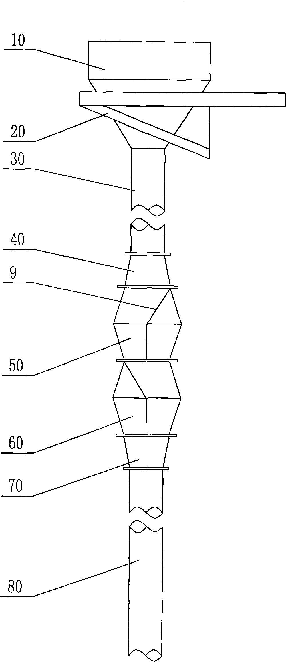
[0005] However, the My-Box descender also has the following problems when it is used. Because the My-Box descender is usually made of high-quality wear-resistant steel, when the concrete is conveyed vertically downward, the concrete and the shell of the descender and the partition The plates are all in direct contact with friction, so they wear quickly, and they need to be replaced or repaired frequently when a large amount of concrete is poured, which greatly increases the cost of manufacturing and maintenance, and also greatly affects the construction progress and construction quality.

Method used


Image

  • Concrete vertical conveying descent control device
  • Concrete vertical conveying descent control device
  • Concrete vertical conveying descent control device

Examples


Embodiment Construction

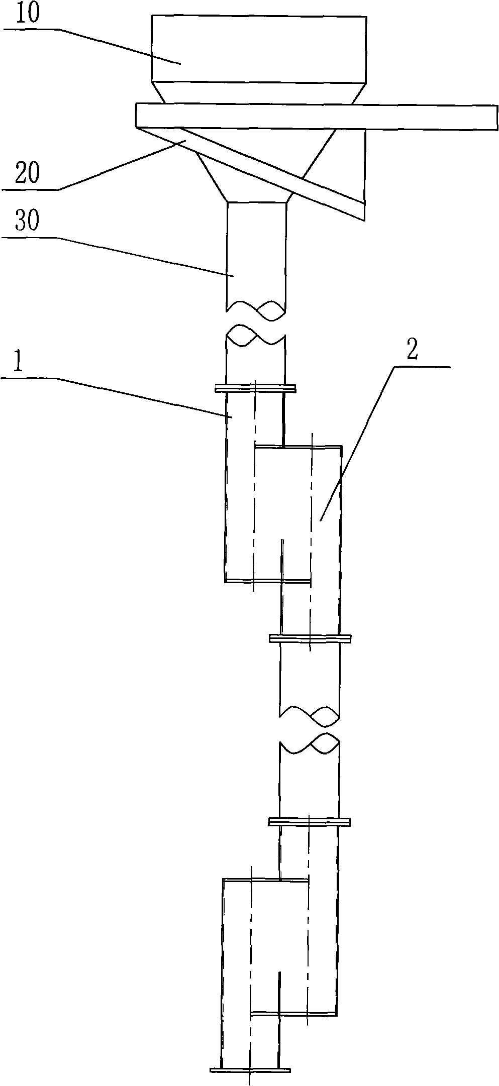
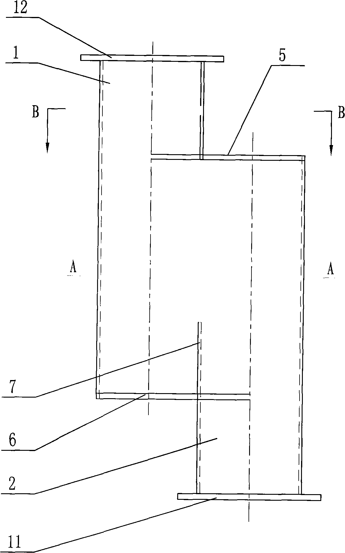
[0026] Such as Figure 3 ~ Figure 6 As shown, a concrete vertical conveying slow down device of the present invention includes a left round pipe 1 and a right round pipe 2, the centerlines of the left round pipe 1 and the right round pipe 2 are parallel, and the two are at a height of The direction is dislocated; the left round tube 1 and the right round tube 2 are provided with a certain length of arc-shaped incision; An arc-shaped incision with a certain distance from the end surface and an inverted L-shaped section; the incision on the right circular tube is an arc-shaped incision located on the left side of the center line, a certain distance from the upper end surface of the right circular tube, and an L-shaped cross-section incision. The cutout on the left round pipe 1 corresponds to the cutout on the right round pipe 2 in the length direction, and the two correspond on the front and rear sides, and the front connecting plate 3 and the rear connecting plate 4 made of re...


PUM


Abstract

The invention discloses a descent control device for vertically conveying concrete, which comprises a left circular tube and a right circular tube; the central lines of the left circular tube and the right circular tube are in parallel and the left circular tube and the right circular tube are arranged alternately at the direction of height; cuts of certain length are arranged on both the left circular tube and the right circular tube; the cut on the left circular tube and the cut on the right circular tube correspond to each other at the direction of length; in addition, the front lateral sides and the rear lateral sides of the cut on the left circular tube and the cut on the right circular tube are correspond to each other and connected with each other by a front-side connecting plate and a rear-side connecting plate; the upper end parts and the lower end part of the left circular tube and the right circular tube are connected with an upper sealing board and a lower sealing board correspondingly; the left circular tube and the right circular tube form a communicated containing cavity by the corresponding connection of the front-side connecting plate, the rear-side connecting plate, the upper sealing board and the lower sealing board; the inner surface of the lower sealing board is provided with a clapboard in parallel to the central lines of the circular tubes at two sides. When used for vertically conveying concrete, the descent control device can prevent the concrete from separating, effectively improves the workability of the concrete; the descent control device has long service life, no frequent examination and repair or replacement, simple structure and low manufacturing cost.

Description

technical field [0001] The invention relates to the technical field of concrete vertical conveying systems, in particular to a concrete vertical conveying slow descender. Background technique [0002] At present, in the construction of water conservancy and hydropower, highways, municipalities, underground railways and other projects, concrete must be poured, and concrete is transported in the vertical direction, and it usually needs to overcome the drop of tens of meters or even hundreds of meters. During the process, due to the gravity of the concrete itself, the aggregate in the concrete will be separated, resulting in poor workability of the concrete, which greatly affects the quality of the concrete pouring, and the pouring effect cannot be guaranteed. [0003] In the existing technology, in order to solve the problem of aggregate separation when concrete is transported in the vertical direction, the country has successfully introduced the My-BOX slow-down device techno...

Claims


Application Information

Patent Timeline
Patent Type & Authority Applications(China)
IPC IPC(8): E04G21/02
Inventor 马勋才马山玉刘芳明邱东明方勇锋
Owner SINOHYDRO BUREAU 14 CO LTD
Learn More