Eureka AIR delivers breakthrough ideas for toughest innovation challenges, trusted by R&D personnel around the world.

Method for monitoring automatization discriminating video

A video monitoring and frequent technology, applied in the direction of closed-circuit television system, cooperative operation device, measuring device, etc., can solve the problems of labor cost expenditure, high cost, low accuracy rate, etc., to save human resource cost and save cost , the effect of high accuracy

Inactive Publication Date: 2008-10-08
SHANGHAI JIAO TONG UNIV
View PDF0 Cites 23 Cited by
  • Summary
  • Abstract
  • Description
  • Claims
  • Application Information

AI Technical Summary

Problems solved by technology

This system has four major disadvantages: First, it requires an operator to monitor the video collected by monitoring equipment such as video cameras or digital cameras in real time. The cost of monitoring equipment is high, and labor costs must be borne, otherwise the early warning function of real-time monitoring will be lost.
Its shortcomings are: 1. It is required that the tracked object must have an electronic tag, but most of the objects in the video surveillance system are uncertain, and it is impossible to identify the object with an electronic tag in advance
3. This method uses active tags. First, it consumes a lot of energy, and second, it is expensive.
However, this article is only a theoretical discussion and cannot be directly applied to the actual video surveillance system. The specific performance is: no real-time monitoring function is provided, so it is impossible to talk about how to monitor in real time; the time complexity is high, the system executes slowly and The accuracy rate is not high; the use of active electronic tags is not only costly, but also consumes a lot of energy, ignoring the requirements of environmental protection

Method used


Image

  • Method for monitoring automatization discriminating video

Examples


Embodiment Construction

[0027] The embodiments of the present invention are described in detail below in conjunction with the accompanying drawings: this embodiment is implemented on the premise of the technical solution of the present invention, and detailed implementation methods and specific operating procedures are provided, but the protection scope of the present invention is not limited to the following the described embodiment.

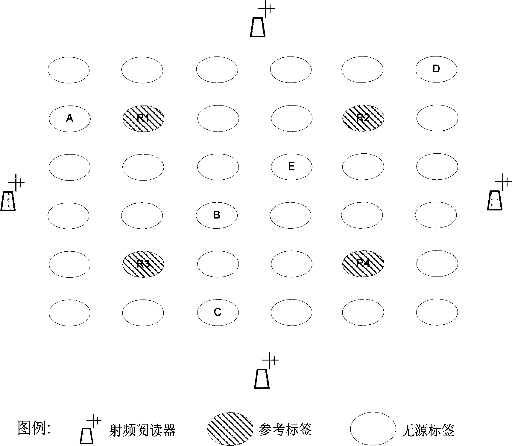
[0028] The tags and readers used in this embodiment are all from the products of Alien Company in the United States, and work at a frequency of 433Mhz. The chip of the electronic tag is modified to add and store some additional information. The whole implementation process is as follows:

[0029] 1. Arrange the reference tag array: 81 electronic tags, including 9 reference tags that are active tags and 72 passive tags. First arrange 81 electronic tags into a 9x9 array, and there is a reference tag in every 9 tags. Labels are spaced 2m apart in both row and column. ...


PUM


Abstract

An automatization discriminating video monitoring method has the steps: first building a refernence label array, adjusting the power of the RF reader to ensure the reading range to entirely cover the label array; then computing the mean of each electrical label signal intensity in the refernence label array and the signal intensity changing range when objects passby, getting the signal intensity threshold through the statistical analysis; and then, recording the signal intensity of all the labels including the refernence label in the whole monitoring process, and forming the signal intensity sequence through completing the missing items anf removing the abnormal value; reconverting the signal intensity sequence to form the trace set, and generating the frequent trace set from the trace set; finally judging the present behavior to be the permissive activity by the system through the detecting process. The invention not only provides the similar accuracy as the traditional art, but also provides the realtime monitoring function, saves the cost of human resources and the cost of the video realtime discriminating technology.

Description

technical field [0001] The invention relates to a monitoring method in the field of radio frequency technology, in particular to an automatic identification video monitoring method. Background technique [0002] Radio frequency technology is an automated identification technology that is widely used in object tracking, supply chain management, security control, and animal identification. The radio frequency reader can automatically detect objects marked with radio frequency electronic tags within its reading and writing range, and read and write the information stored in the electronic tags. However, the application requirements of radio frequency are: the monitored objects must be equipped with electronic tags in advance, and the monitored objects in the video surveillance system are mostly uncertain, especially in security monitoring, it is impossible to use electronic tags to identify objects in advance, so There are few studies on the application of RF to video surveill...

Claims


Application Information

Patent Timeline
Patent Type & Authority Applications(China)
IPC IPC(8): G08B21/00G01S5/02H04N7/18G06K17/00
Inventor 张大强过敏意管虎周憬宇唐飞龙
Owner SHANGHAI JIAO TONG UNIV
Why Eureka
Eureka Blog
Learn More