Engine generator

An engine and generator technology, applied in the direction of electromechanical devices, electrical components, electric components, etc., can solve the problems of large axial size of engine generators, inconvenient assembly, complex structure, etc., and achieve compact structure, simplified structure, and convenient assembly. Effect

Inactive Publication Date: 2008-10-08
LONCIN MOTOR
View PDF0 Cites 11 Cited by
  • Summary
  • Abstract
  • Description
  • Claims
  • Application Information

AI Technical Summary

Problems solved by technology

For generators of different structures, the installation methods at the end of the crankshaft are different. There are two common types. One is equipped with a large generator with ordinary windings, such as figure 1 Shown, because generator volume is very big, starter 13, flywheel 14, fan 15 and starter cup 16 are positioned at crankshaft 17 one end, and generator is then separately installed on the other end of crankshaft 17 (not shown in the figure), and crankshaft 17 extends The part that goes out of crankcase 18 needs to be done very long, makes the axial dimension of whole motor generator too large; Another kind is to assemble permanent magnet generator, as figure 2 As shown, the generator 19 of this structure is an outer rotor structure, the volume is small, the rotor also doubles as a flywheel, the fan 20 and the starting cup 21 are directly installed on the rotor, and the crankshaft 22 of the engine generator of this structure extends out of the crankcase Although the length of 23 can be shortened, because the rotor of the generator is directly installed on the crankshaft, and the rotor is assembled with components such as a fan and a starting cup, the structure is complex, and there are problems of poor reliability and inconvenient assembly

Method used


Image

  • Engine generator
  • Engine generator
  • Engine generator

Examples


Embodiment Construction

[0011] Below in conjunction with accompanying drawing and embodiment the present invention will be further described:

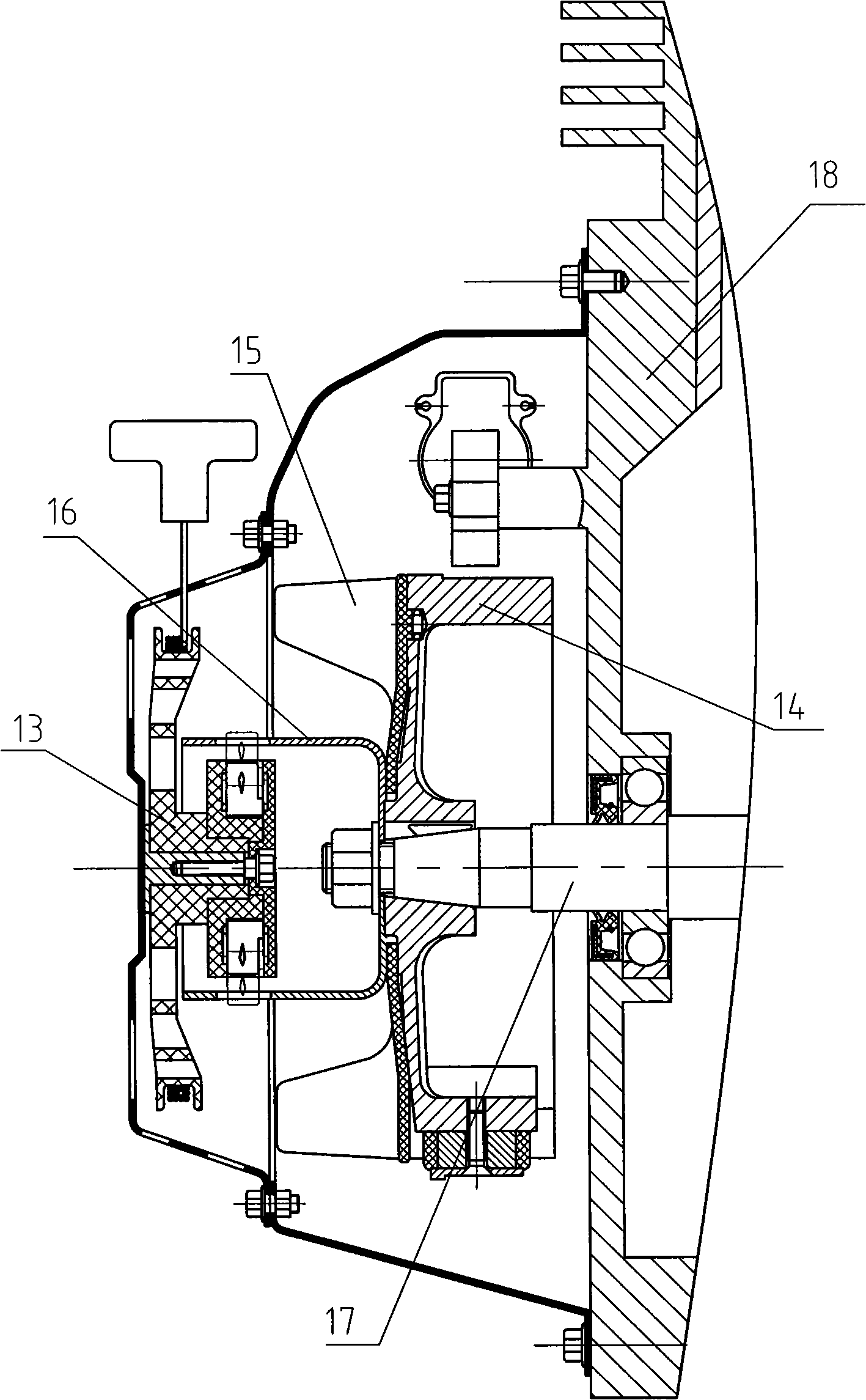
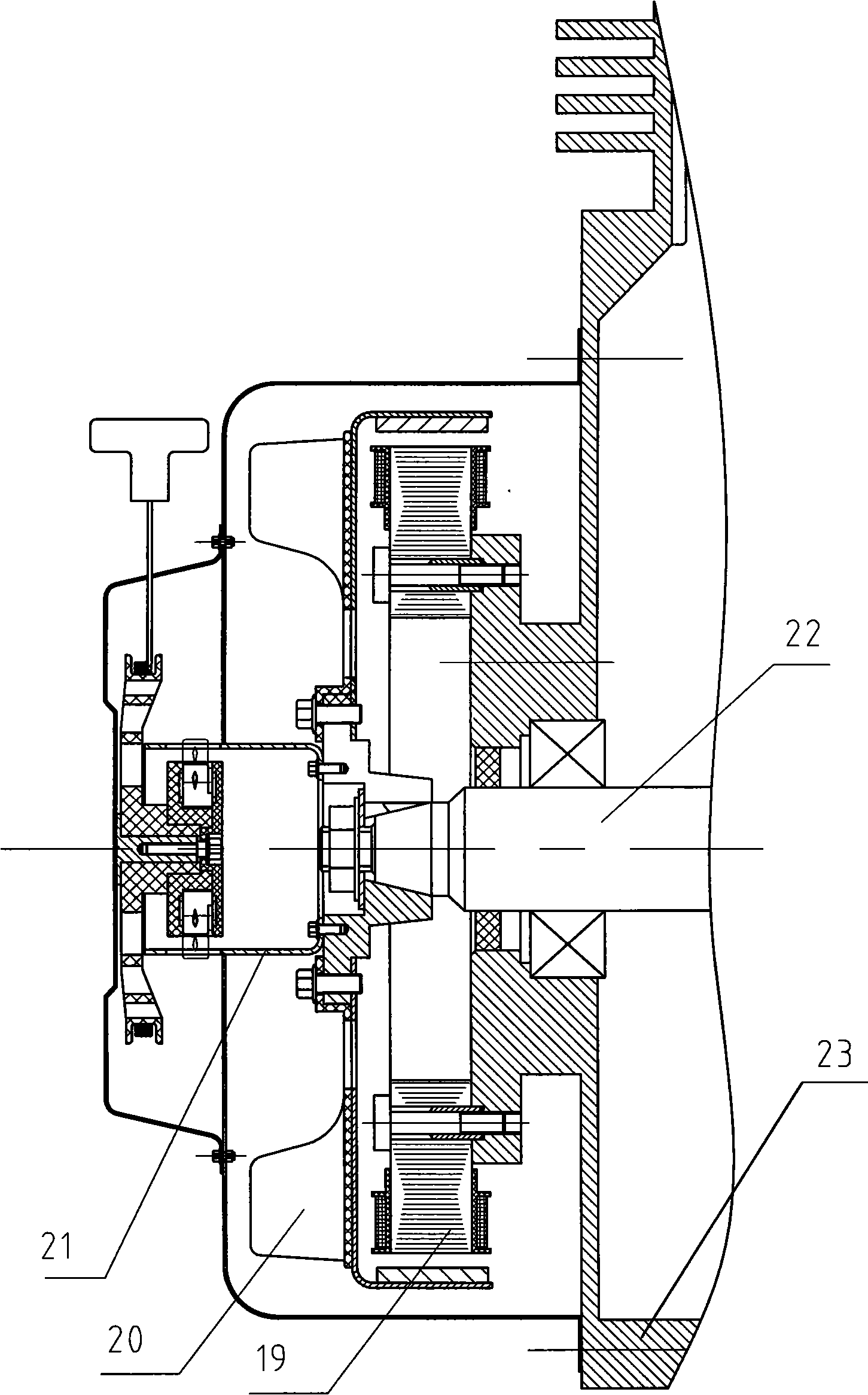
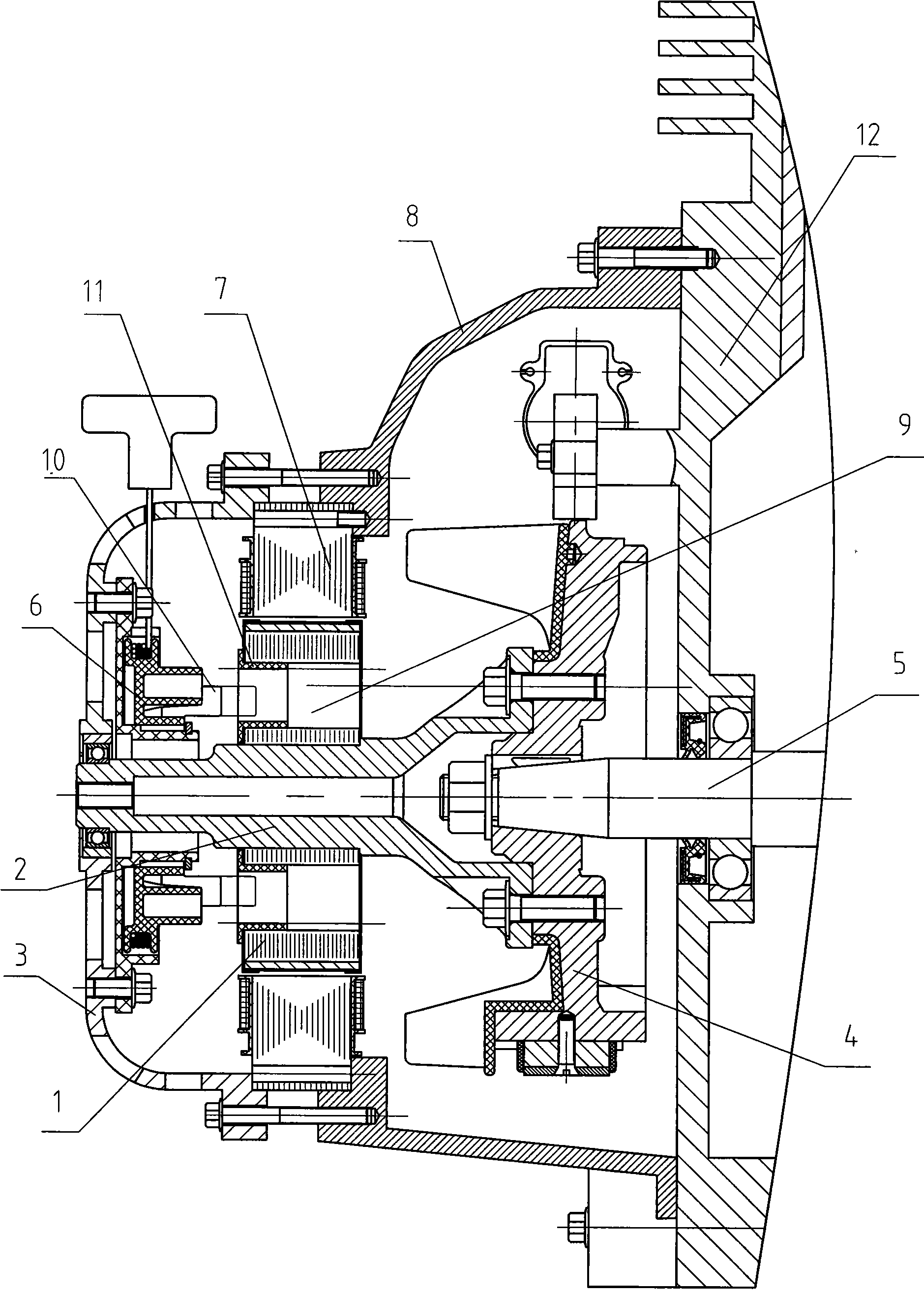
[0012] Such as image 3 As shown, an engine generator, the generator is an inner rotor structure, has a motor, a generator and a starter for starting the engine, the generator and the starter are arranged outside the crankcase of the engine and are coaxially located in the axial direction of the crankshaft On the same side of the engine crankshaft protruding from the crankcase, a flywheel is installed at one end of the crankshaft. The generator is located between the starter and the flywheel. The generator is an inner rotor structure. The generator rotor 1 is supported on the rotor shaft 2 detachably connected to the flywheel 4. Above; the iron core of the generator rotor 1 is provided with an axial hole 9 , and the axial hole 9 corresponds to the position of the axially displaceable ratchet 10 on the starter 6 .

[0013] Because generator rotor 1 is separat...


PUM


Abstract

An engine generator has an engine, a generator and a starter 6 for starting the engine, the generator and the starter are arranged outside the engine crankshaft 12 and coaxial at the same side of the engine crankshaft 5 axial direction, one end of the engine crankshaft 5 protruding out the crankshaft 12 is provided with a flywheel 4, the generator is positioned between the starter 6 and the flywheel 4, the generator is of inner rotor structure, the generator rotor 1 is supported on the rotor shaft 2 dismountable connecting with the flywheel 4; an axial hole 9 is provided on the iron core of the generator rotor 1, the axial hole 9 is relative to the position of a ratchet 10 which can axial move on the starter 6. The invention has compact structure and convenient installment, can make the axial size of the engine crankshaft shorter and simplify the structure.

Description

technical field [0001] The invention relates to a generator, in particular to a generator driven by an engine. Background technique [0002] The stator and rotor of the existing engine generator are usually installed on one end of the crankshaft of the engine protruding from the crankcase, and the rotor is directly or indirectly driven by the crankshaft. The hand starter used to start the engine is located on the outermost side and is coaxial with the crankshaft. When starting, the pawl of the hand starter drives the crankshaft to rotate through the start cup installed at the end of the crankshaft. For generators of different structures, the installation methods at the end of the crankshaft are different. There are two common types. One is equipped with a large generator with ordinary windings, such as figure 1 Shown, because generator volume is very big, starter 13, flywheel 14, fan 15 and starter cup 16 are positioned at crankshaft 17 one end, and generator is then separa...

Claims


Application Information

Patent Timeline
Patent Type & Authority Applications(China)
IPC IPC(8): H02K7/118H02K7/02H02K7/18
CPCH02K7/1807H02K7/118
Inventor 王虎山唐真兴何飞隆郁
Owner LONCIN MOTOR
Why Eureka
Try Eureka