High speed dish type circular valve highly effective slag draining and separating machine

A slag separation and separation mechanism technology, applied in centrifuges with rotating drums, centrifuges, etc., can solve the problems of insufficient material strength, waste of human resources, long production cycle, etc., and achieve strong economic competitiveness and technology. Advantages, simple structure and production process, and the effect of a small number of parts

Inactive Publication Date: 2008-10-15
无锡市减速机械有限公司
View PDF0 Cites 19 Cited by
  • Summary
  • Abstract
  • Description
  • Claims
  • Application Information

AI Technical Summary

Problems solved by technology

[0003] The defects of the separation mechanism and the transmission method used are: 1. Complex structure, difficult manufacture, long production cycle, and the number of processed parts reaches about 150
2. It consumes a lot of steel and non-ferrous metals, wastes human resources and increases energy consumption
3. Due to the high precision requirements of the gear transmission, the maintenance is complicated, which increases the repair cost
4. It is easy to generate vibration and noise when running at high speed
5. In order to improve the corrosion resistance, the main parts of the separator are made of stainless steel. Due to the insufficient strength of the material, the increase of the rotating speed is limited.

Method used


Image

  • High speed dish type circular valve highly effective slag draining and separating machine
  • High speed dish type circular valve highly effective slag draining and separating machine
  • High speed dish type circular valve highly effective slag draining and separating machine

Examples


Embodiment Construction

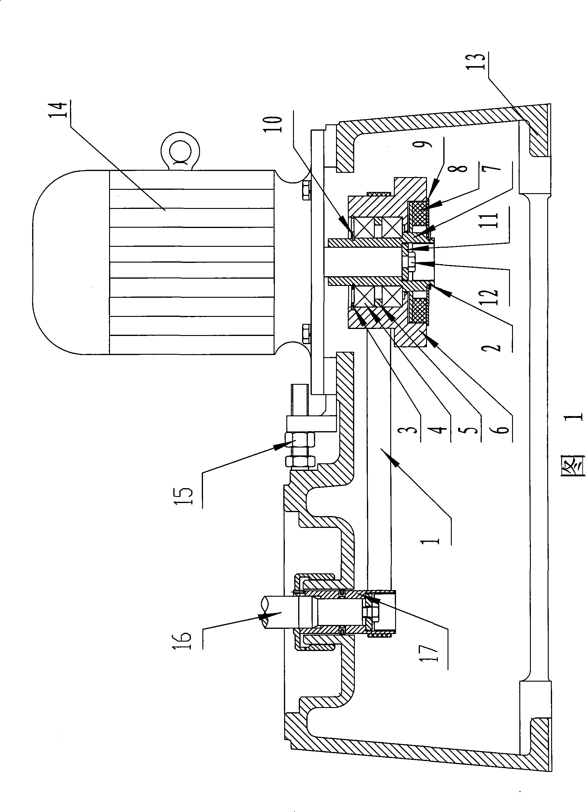
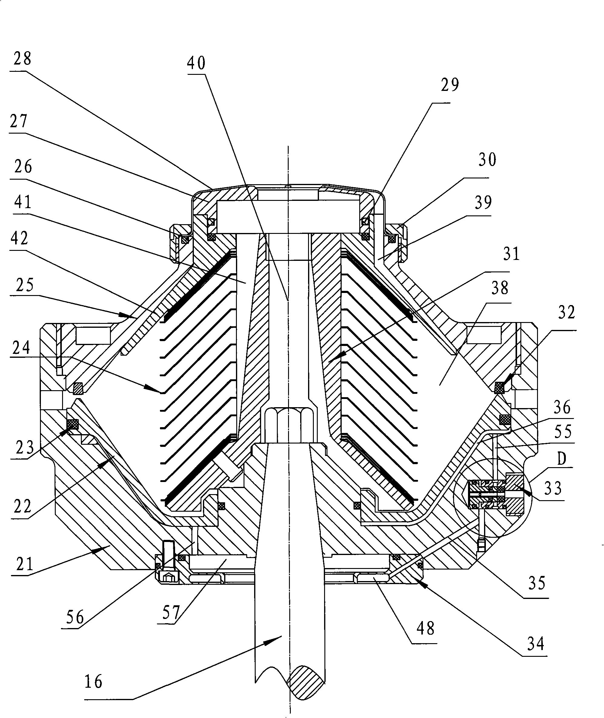
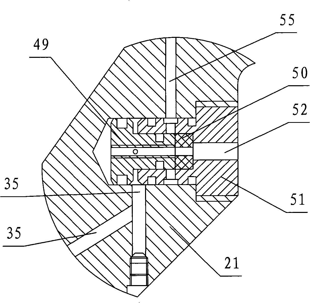
[0021] As shown in Figures 1 and 2: a separation mechanism and a transmission mechanism thereof are installed on the base 13; 21 and the cylinder cover 25 form a separation cavity 38, and a disc frame 31 with a sewage inlet channel 40 is arranged in the center of the separation cavity 38, and a number of inverted discs 24 are arranged on the outer wall of the disc frame 31. A piston 22 that can slide up and down relative to the separation cylinder 21 is arranged on the top, a slag discharge port 37 is provided on the separation cylinder 21 or the cylinder cover 25, and a control channel 35 is arranged in the separation cylinder 21, and the control channel 35 is formed in the piston 22 and the separation cylinder. The gap 36 between 21 communicates, and the control valve 33 for closing or opening the control channel 35 is set on the control channel 35. When the control valve 33 is opened, the high-pressure fluid at the bottom of the piston 22 enters the control valve 33 through ...


PUM


Abstract

The invention relates to a separation machine, in particular to a high-speed disc type ring valve high-efficient slag-discharge separator. The technical proposal provided by the invention is that, a separation mechanism and a transmission mechanism thereof are arranged on a base; a separation cylinder in the separation mechanism is arranged on a vertical shaft, a cylinder cover is arranged on the separation cylinder, a separation cavity is formed between the separation cylinder and the cylinder cover, a disc rack with a sewage inlet channel at the interior is arranged at the center of the separation cavity, a plurality of discs covered reversely are arranged on the outer wall of the disc rack, a piston which can slide up and down relative to the separation cylinder is arranged at the upper surface of the separation cylinder, and a slag discharge port is formed on the separation cylinder; the separator is characterized in that: a control channel is arranged in the separation cylinder, the control channel communicates with a gap formed between the piston and the separation cylinder, a control valve for closing or opening the control channel is arranged on the control channel, when the control valve is opened, high-pressure fluid positioned at the bottom part of the piston enters the control valve to be discharged for pressure relief by a pressure relief channel, thus descending the piston and opening the slag discharge port. The separator can simplify structure, reduce energy consumption and facilitate maintenance.

Description

technical field [0001] The invention relates to a separation machine, in particular to a high-speed disc-type ring valve high-efficiency slag discharge separator. Background technique [0002] At present, domestically produced separators such as Figure 4 As shown: the separation cylinder 21 is installed on the vertical shaft 16, the cylinder cover 25 is arranged on the top of the separation cylinder 21, and the separation cavity 38 is formed between the separation cylinder 21 and the cylinder cover 25, and a sewage inlet channel is provided in the center of the separation cavity 38 40 disc frame 31, a number of undercut discs 24 are set on the outer wall of the frame 31, a piston 22 that can slide up and down relative to the separation tube 21 is set on the top of the separation tube 21, and a row The slag outlet 37 and its slag discharge mechanism are composed of a nylon valve 63, an action slide block 60, 12 action springs 61, and a spring seat 62, which are fixedly insta...

Claims


Application Information

Patent Timeline
Patent Type & Authority Applications(China)
IPC IPC(8): B04B1/04B04B7/00B04B9/08B04B11/00
Inventor 周振华李建设
Owner 无锡市减速机械有限公司
Why Eureka
Try Eureka