
Numerical control sponges cutting machine

A technology of sponge cutting machine and frame, applied in metal processing, using vibrating fluid, etc., can solve the problems of difficult processing of sponges with complex shapes, and achieve the effects of great practical and popular value, consistent vibration frequency and reasonable structure.

Active Publication Date: 2008-10-15
NANTONG MUYE MACHINERY
View PDF1 Cites 17 Cited by
  • Summary
  • Abstract
  • Description
  • Claims
  • Application Information

AI Technical Summary

Problems solved by technology

Existing sponge cutting machines generally use blades for cutting and processing. Due to its structure, it can only process sheet or strip sponges, and it is difficult to process sponges with complex shapes.
my country's patent application, the application number is: 200610037419.X, the name is called: "cutter head vibration type cutting sponge mechanism" discloses a kind of equipment that adopts left and right workbenches and vertical and horizontal knives to combine to cut sponge, although this equipment The three-dimensional processing of sponge has made great progress, but due to structural reasons, the vertical and horizontal two knife belts can only process the sponge in a straight line perpendicular to the workbench. The shape is difficult to meet the design requirements, so it is necessary to improve the existing sponge processing equipment to meet the actual needs

Method used


Image

  • Numerical control sponges cutting machine
  • Numerical control sponges cutting machine
  • Numerical control sponges cutting machine

Examples


Embodiment Construction

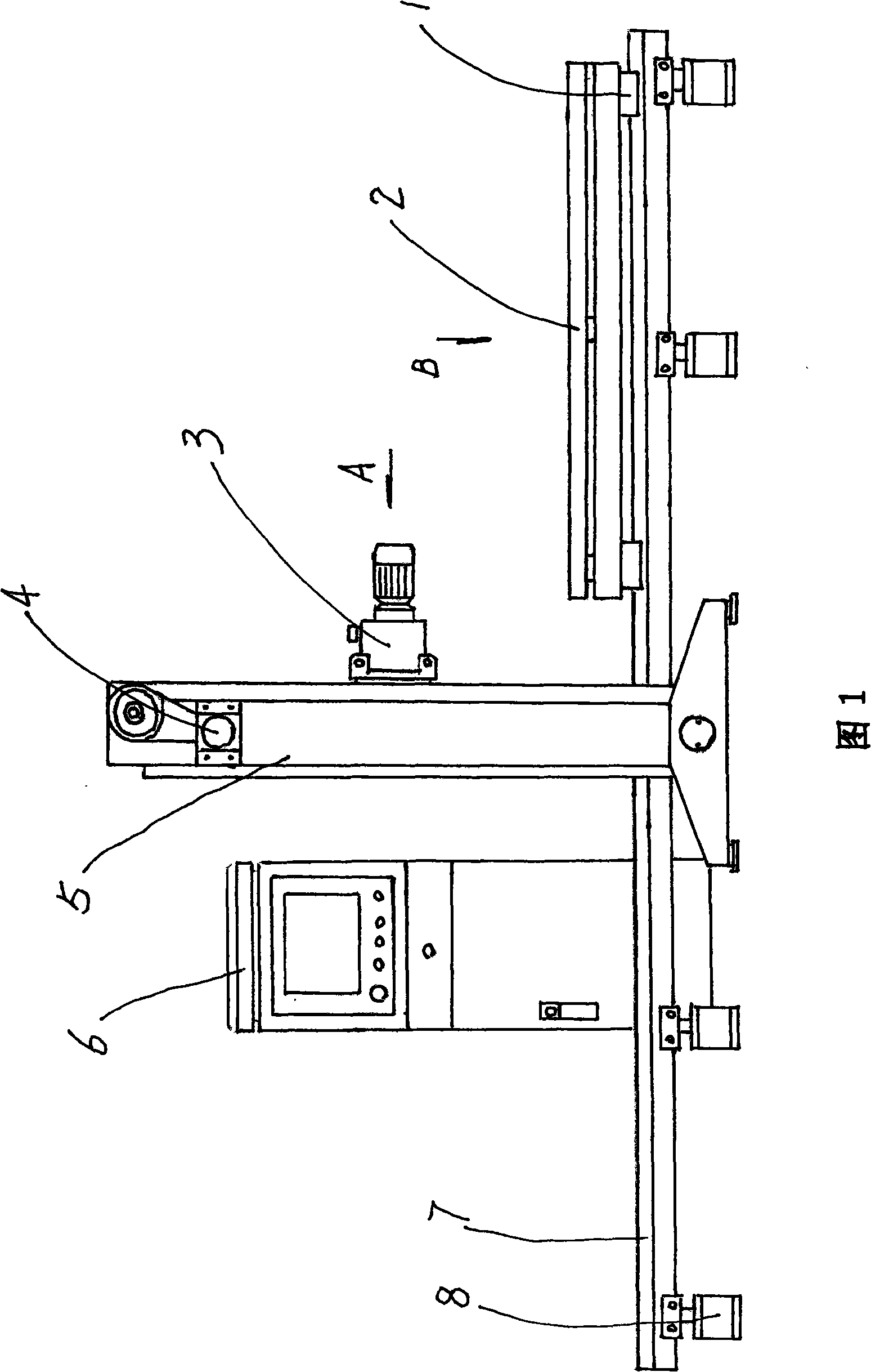
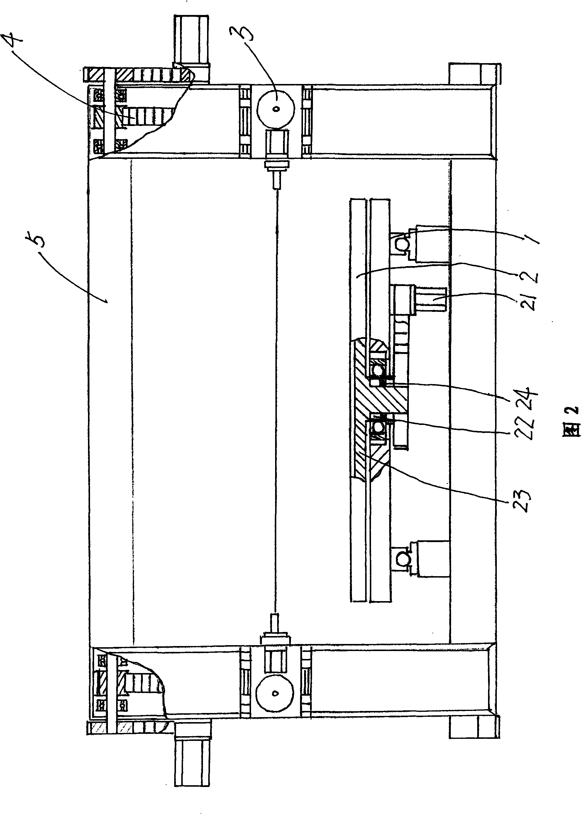
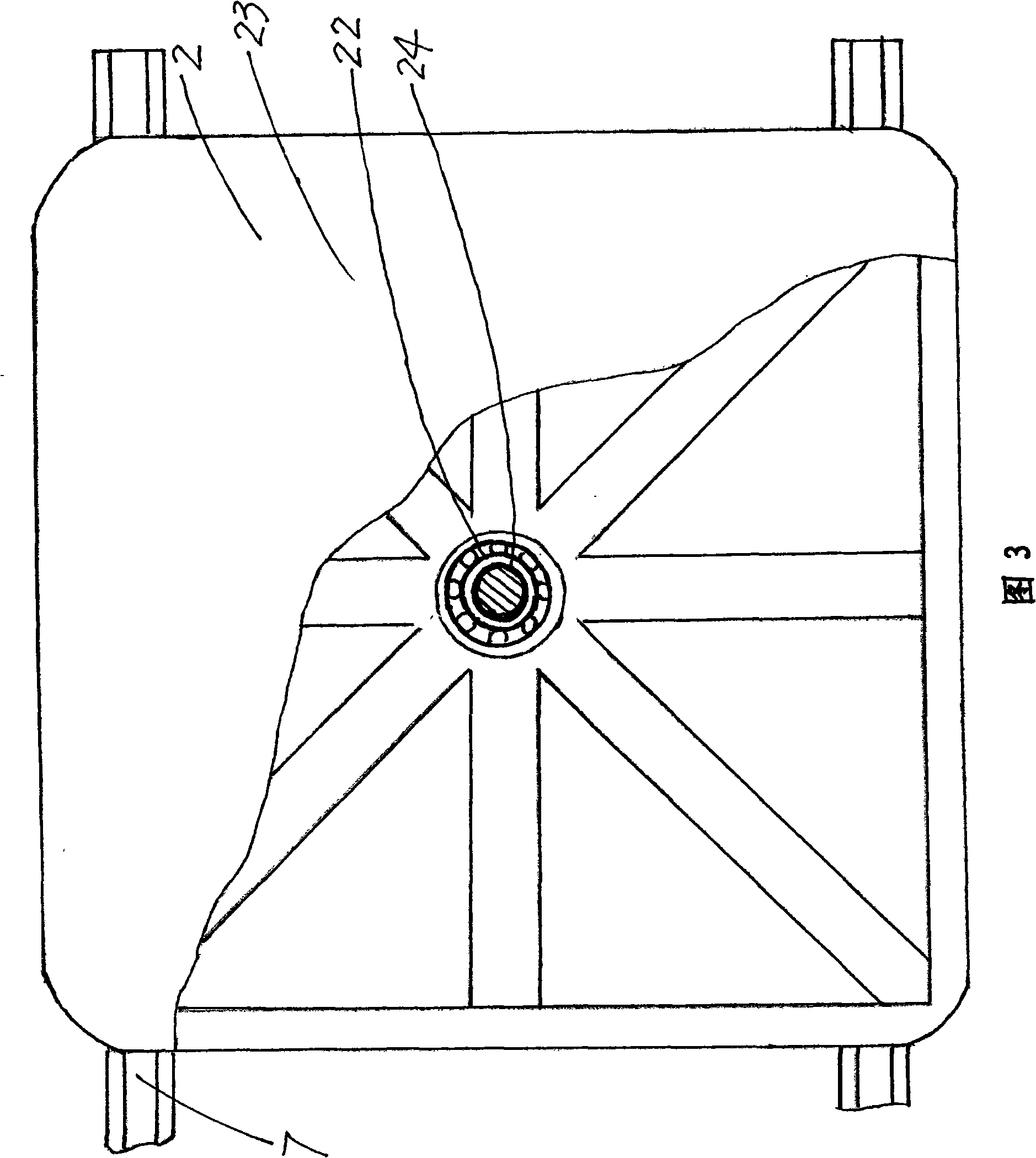
[0024] With reference to accompanying drawing 1, accompanying drawing 2, accompanying drawing 3, numerical control sponge cutting machine of the present invention, by workbench base 1, rotating workbench 2, vibration device 3, vertical traction device 4, door frame 5, control part 6, horizontal The guide rail 7 and the frame 8 are composed of a workbench base 1 arranged on the horizontal guide rail 7, and can move horizontally along the horizontal guide rail 7; The workbench 2 is a workbench that can be lifted and rotated on the workbench base 1. The rotary workbench 2 is composed of a rotary drive device 21, a lift cylinder part 22, a workbench 23, and a piston 24. The cylinder liner of the lift cylinder part 22 supports On the workbench base 1, the rotary drive device 21 is fixed on the workbench base 1, and the rotary drive device 21 drives the drive gear on the workbench 23 through the drive belt; The inlet and outlet of the liquid; the shaft of the workbench 23 is provide...


PUM


Abstract

The invention relate to a numerical control sponge cutting machine, which comprises a workbench base, a rotary workbench, vibration devices, vertical pulling devices, a gantry, a control part, a horizontal guide rail and a rack. The workbench base is arranged on the horizontal guide rail and the rotary workbench capable of lifting and rotating is arranged on the workbench base; the two vertical pulling devices are arranged on the gantry, and the two vibration devices are respectively arranged on two columns of the gantry; the control part is a numerical control system. Since the two vertical pulling devices are adopted to respectively adjust the height and the position of the two vibration devices, the sponge cutting machine is capable of processing sponge of different heights; since the workbench has a structure capable of lifting and rotating, the sponge cutting machine is capable of processing sponge of various curves; since the combination of adjusting cylinders and dampers is adopted in the vibration devices, the sponge cutting machine has more reliable cutting and the reasonable structure leads to non-environment pollution and high automatization, therefore, the sponge cutting machine is of great utility and popularization value.

Description

technical field [0001] The invention relates to a device for processing sponges, in particular to a numerically controlled sponge cutting machine. Background technique [0002] After retrieving relevant patent documents, no numerically controlled sponge cutting machine with the same structure as the present invention has been retrieved yet. Existing sponge cutter generally adopts blade to cut and process, because the reason of its structure can only process sheet or strip sponge, then is difficult to process for the sponge of complex shape. my country's patent application, the application number is: 200610037419.X, the name is called: "cutter head vibration type cutting sponge mechanism" discloses a kind of equipment that adopts left and right workbenches and vertical and horizontal knives to combine to cut sponge, although this equipment The three-dimensional processing of sponge has made great progress, but due to structural reasons, the vertical and horizontal two knife b...

Claims


Application Information

Patent Timeline
Patent Type & Authority Applications(China)
IPC IPC(8): B26D5/00B26D7/20B26D7/08B06B1/12
Inventor 缪仪
Owner NANTONG MUYE MACHINERY
Learn More