Solution casting method and apparatus

一种溶液、流延的技术,应用在应用、涂层、家里用具等方向,能够解决厚度不均匀性的质量允许程度变高等问题,达到降低厚度不均匀性、高质量、抑制振动的效果

Inactive Publication Date: 2008-10-15
FUJIFILM CORP
View PDF4 Cites 13 Cited by
  • Summary
  • Abstract
  • Description
  • Claims
  • Application Information

AI Technical Summary

Problems solved by technology

[0005] However, according to recent improvements in image definition of flat panel displays (FPDs), the quality tolerance of thickness unevenness has become higher
Therefore, sufficient quality cannot be achieved by using the solution casting method disclosed in Japanese Patent Laid-Open Publication 2001-18241

Method used


Image

  • Solution casting method and apparatus
  • Solution casting method and apparatus
  • Solution casting method and apparatus

Examples


Embodiment 1

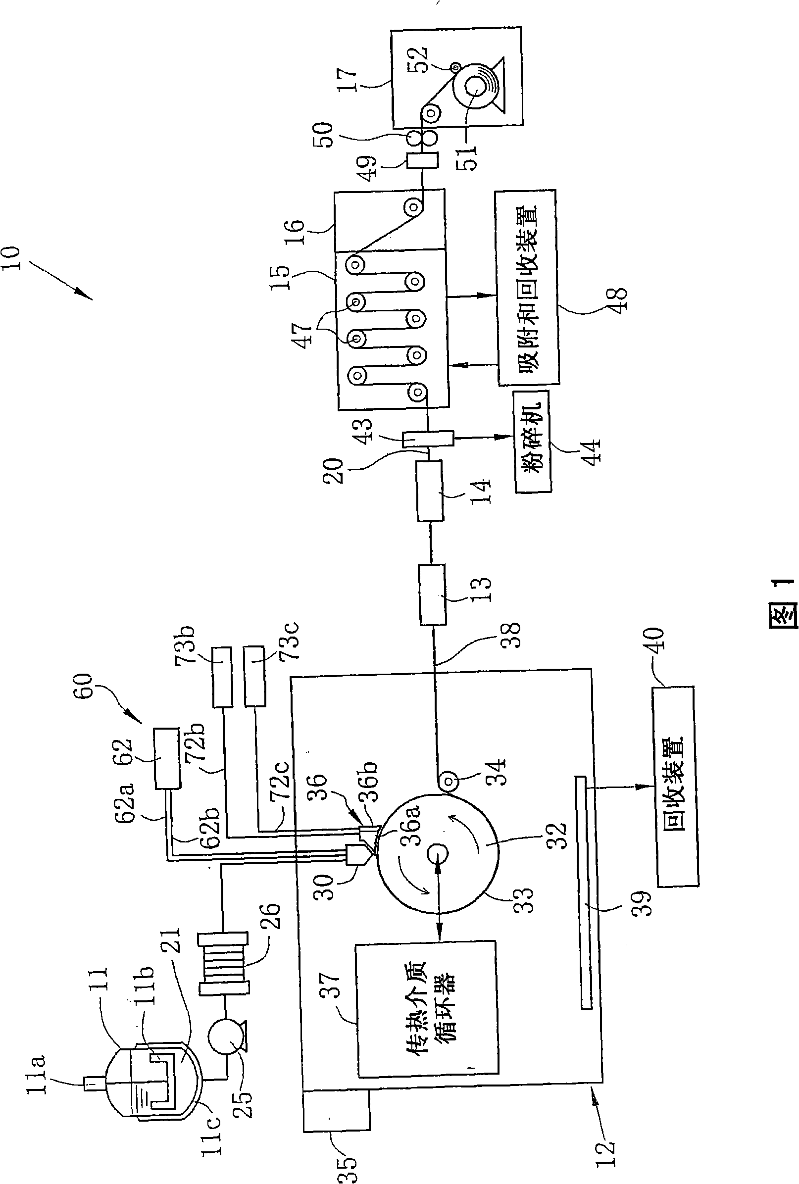
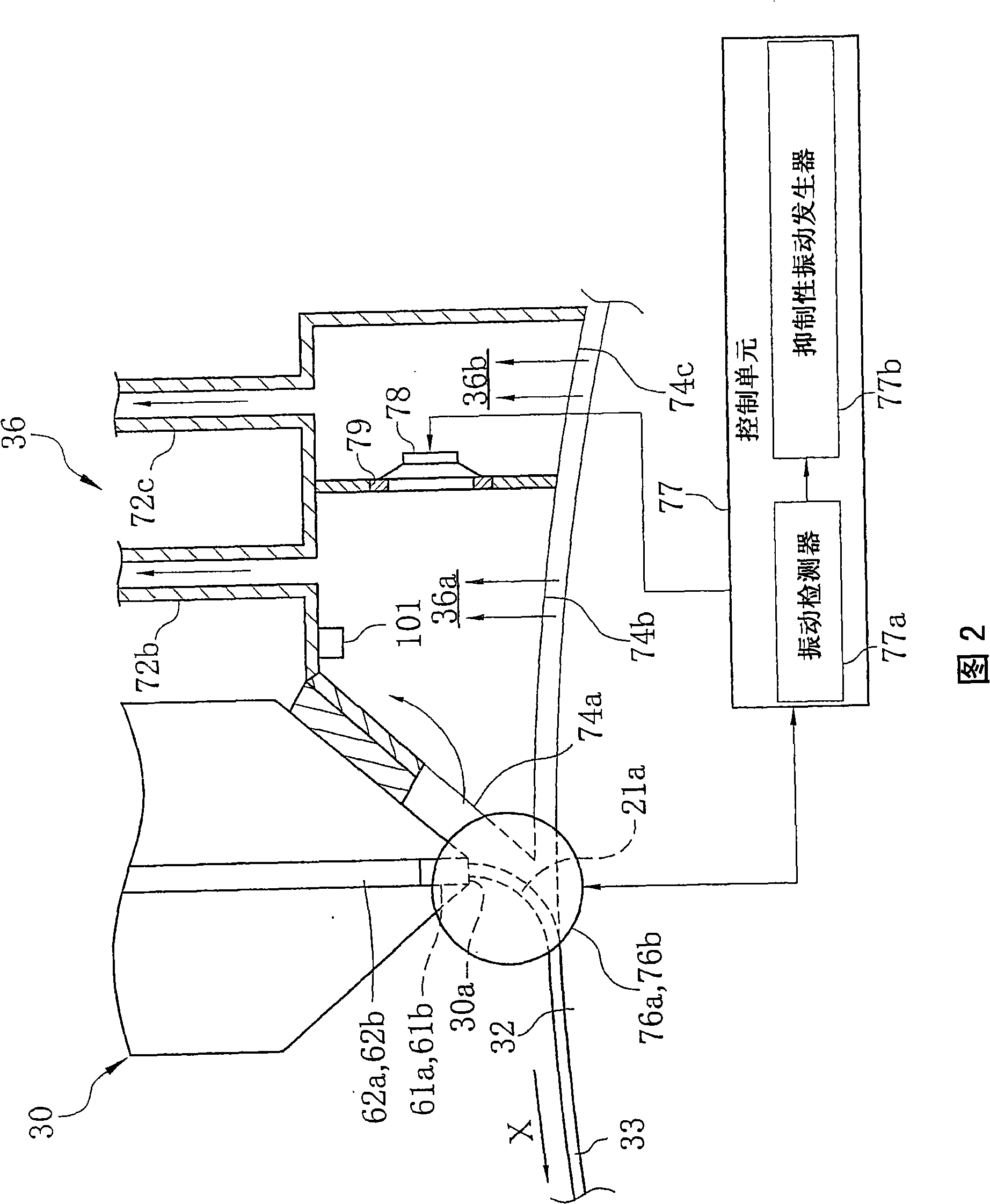
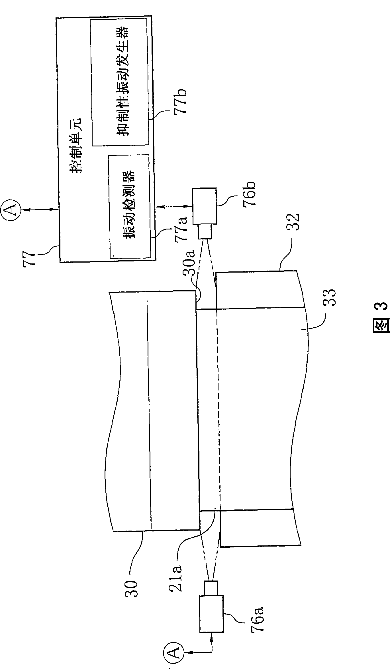
[0090] A decompression chamber 36 shown in FIG. 6 is installed in the film production line 10 . Based on the air pressure information from the air gauge 101 , suppressive vibration is applied to the casting bead 21 a. Films were formed under the following conditions. The distance "h" between the casting die 30 and the casting drum 32 is 3.5mm, the decompression degree "p" of the decompression chamber 36 is -40Pa, the viscosity of the coating is 45Pa·s for the "μ", and the die lip The gap "c1" was 0.9 mm, the casting speed "v" was 50 m / min, and the thickness "t" of the base was 80 μm. At this time, it was detected that the static pressure fluctuation range (amplitude) ΔP of the decompression chamber 36 was 2.4 Pa when the tape length (the length of the casting bead) thereof was 19 mm. A suppressive vibration having an amplitude ΔP of 1.5 Pa, the phase of which is opposite to that of the vibration of the casting bead was applied to and, as a result, was periodically generated ...


PUM

PropertyMeasurementUnit
roughnessaaaaaaaaaa
diameteraaaaaaaaaa

Abstract

A camera for capturing a casting bead is provided at each side end of a discharge port in a width direction thereof. Plural speakers are provided at the vicinity of an opening of a decompression chamber. The camera continuously captures the casting bead, and outputs image data thereof to a control unit. The control unit includes a vibration detector and a suppressing vibration generator. The vibration detector detects vibration of the casting bead based on the plural image data. The suppressing vibration generator generates suppressing vibration signal representing the phase and amplitude of the suppressing vibration for suppressing the vibration generated in the thickness direction of the casting bead. The control unit controls the speakers based on the suppressing vibration signal to output sound wave. Thereby, the suppressing vibration is applied to the casting bead.

Description

technical field [0001] The present invention relates to a solution casting method and equipment, wherein the coating is cast from a casting die in the form of a casting bead onto a carrier to form a casting film, and the solidified casting film is cast from The carrier is peeled off to form a film. Background technique [0002] The solution casting method is widely used in the production of films for optical applications, such as liquid crystal display (LCD) films, organic electroluminescence display (organic EL display) films, polarizer films, and films for photosensitive materials. The solution casting method is as follows. A dope obtained by dissolving cellulose acetate in a solvent is cast onto a support in the form of a casting bead, and the support is moved to form a cast film. After solidification, the cast film was peeled from the support by a peel roll. While being conveyed by using a roll and a tenter, the peeled cast film was dried to form a film. [0003] Acc...

Claims


Application Information

Patent Timeline
Patent Type & Authority Applications(China)
IPC IPC(8): B29C41/24B29C41/34B29C41/52B29L7/00
CPCB29C41/26B29K2001/00B29K2001/12B29K2995/0018B29C41/24
Inventor 片井幸祐
Owner FUJIFILM CORP
Why Eureka
Try Eureka