Boosting pump for steering car

A technology for power steering pumps and automobiles, which is applied to pump components, rotary piston type/swing piston type pump components, components of pumping devices for elastic fluid, etc., which can solve the problem of low output power of the engine at idle and no settings Problems such as pressure switch and easy flameout of the engine can prevent the phenomenon of cavitation and insufficient oil absorption, eliminate the effect that the flow rate cannot be reduced, and the pressure pulse is reduced

Inactive Publication Date: 2008-10-15
郭羽
View PDF0 Cites 2 Cited by
  • Summary
  • Abstract
  • Description
  • Claims
  • Application Information

AI Technical Summary

Problems solved by technology

Due to the structural design of parts, there are the following main defects: First, there is no pressure switch, so that the output power of the engine is small when idling, and the engine is easy to stall when turning the direction
The second is that the oil distribution plate is also prone to noise due to improper design of the oil suction angle
Fourth, the flow rate of the oil outlet nozzle cannot be reduced when the pump is working at high speed and high pressure, and the power consumption is high, which makes the direction of the car flutter when adjusting the driving

Method used


Image

  • Boosting pump for steering car
  • Boosting pump for steering car
  • Boosting pump for steering car

Examples


Embodiment

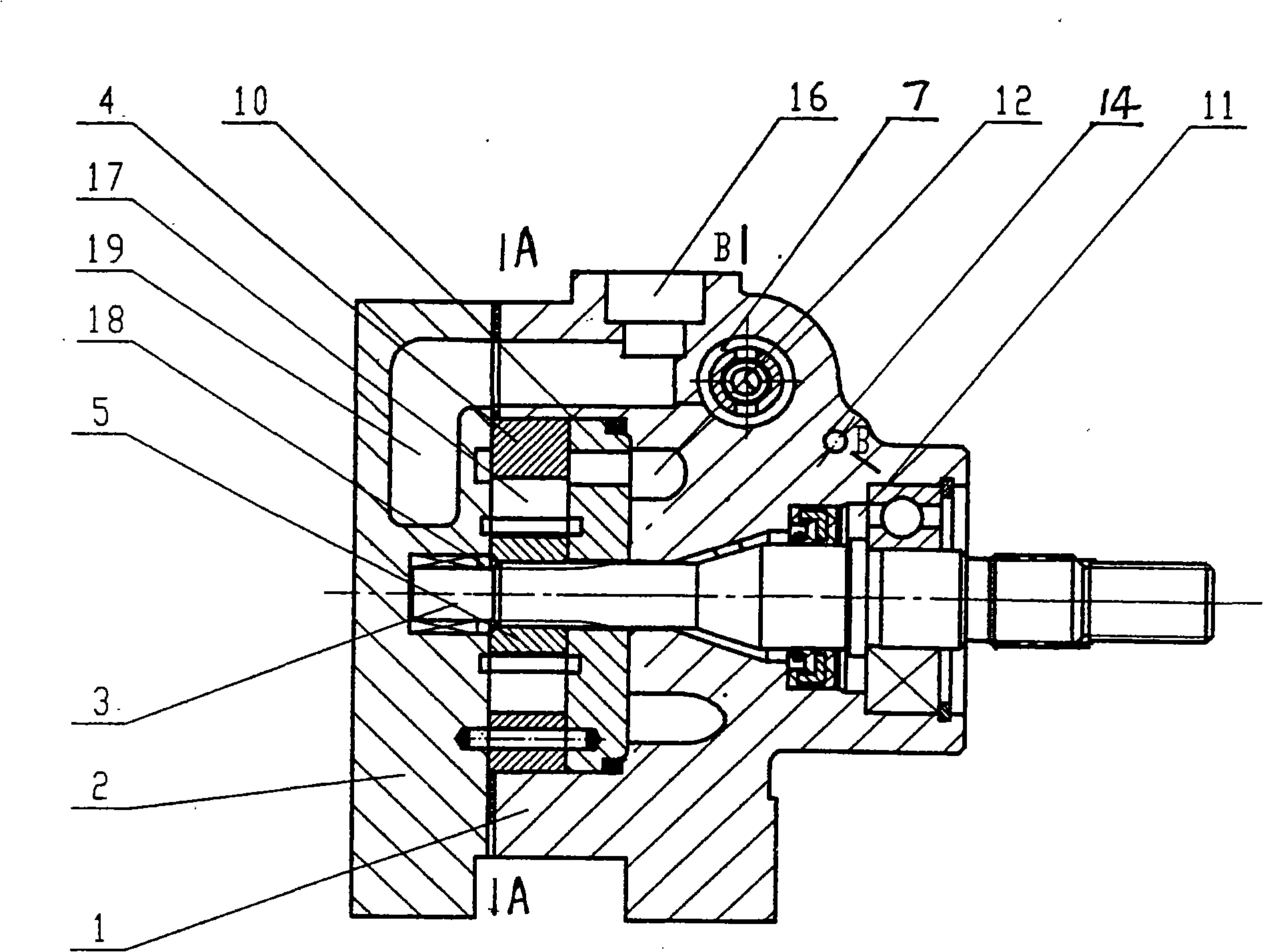
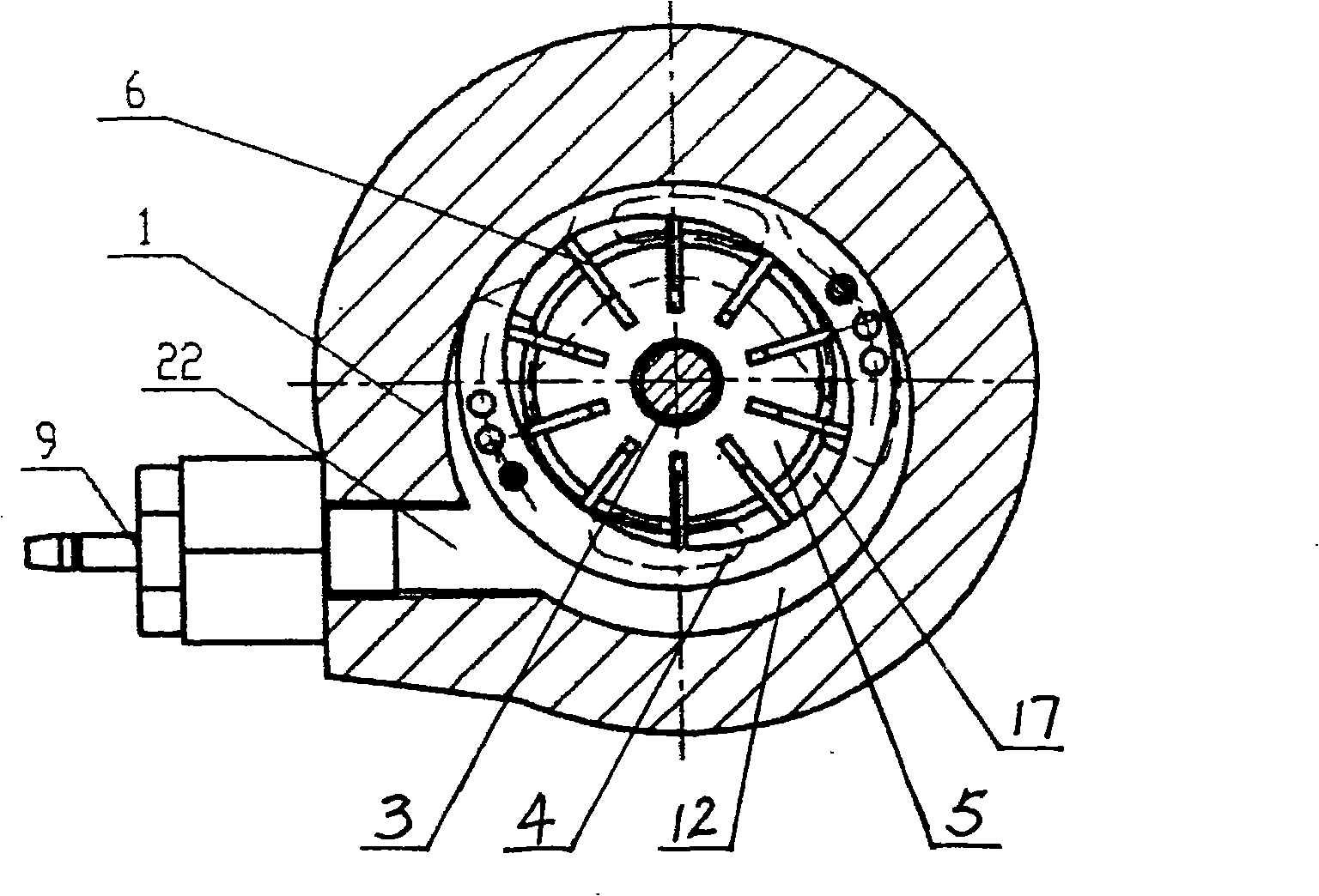
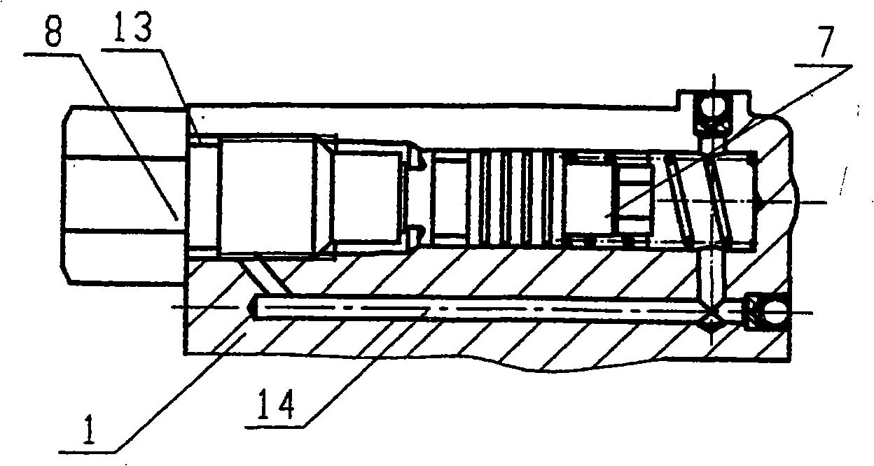
[0026] When working, the engine transmits the torque to the pump shaft 3, driven by the pump shaft 3, the rotor 5 placed in the compression chamber 17 rotates, and the blade 6 inserted in the groove of the rotor 5 is thrown out by centrifugal force and moves along the compression chamber 17. The compression chamber wall slides. Through the oil inlet hole 16 and the oil suction window 27 on the oil distribution plate 10 (angle θ 1 ), the oil in the steering oil pot is sucked into the compression chamber 17 through the oil inlet hole 16 through the oil chamber 19, and then passes through the oil pressure window 28 on the oil distribution plate 10 (angle θ 2 ) hydraulically enters the pump chamber 12, and enters the oil outlet nozzle 8 through the oil introduction hole 14 and the oil outlet hole 13, and the flow is controlled by the throttle body 20 and the slide valve 21 to output to the steering gear within the control flow range of the automobile power steering pump . When t...


PUM


Abstract

The invention discloses an automobile steering boosting pump. The pump comprises a pump body and a pump cover which are in seal connection; the pump body is provided with an oil inlet hole, an oil nozzle with a flow pressure control valve, a pump cavity arranged between the pump body and the pump cover and a pump shaft with a rotor, and is also provided with an oil chamber; the pump cavity is inside provided with an oil distribution disc and a stator with a compression chamber; the oil inlet hole and the oil nozzle form an oil inlet and outlet loop through the oil chamber and the pump cavity; the pump cavity is also provided with an oil conducting hole; the end part of the oil conducting hole is provided with a pressure switch; an outer circle of the stator has a positive circular structure; the middle of the structure is provided with the compression chamber; an outer circle of the oil distribution disc has a positive circular structure; an oil suction window and an oil pressing window which are symmetrical with each other and a sealing region are arranged on the oil distribution disc. The pressure switch consists of a fixed contact and a moving contact; and a spring separates the fixed contact and the moving contact. The oil nozzle is also provided with a throttle body and a slide valve which are separated by a spring. The oil nozzle is communicated with the pump cavity by an oil outlet hole and the oil conducting hole. A groove of the rotor is also provided with blades. The automobile steering boosting pump can be widely applied to various automobiles, engineering machinery, etc.

Description

technical field [0001] The invention relates to an automobile power steering pump, which belongs to the technical field of manufacture of automobile power steering mechanisms. Background technique [0002] With the rapid development of the automobile industry, people have higher requirements for driving comfort and safety, and higher requirements for the performance of automobile hydraulic steering systems. The existing automobile power steering pump is mainly composed of a pump body, a pump cover, a pump shaft, a stator, a rotor, blades, an oil distribution plate, a flow pressure control valve, and the like. Due to the structural design of parts, there are the following main defects: one is that there is no pressure switch, so that the output power of the engine is small when the engine is idling, and the engine is easy to stall when the direction is turned. The second is that the oil distribution plate is also prone to noise due to improper design of the oil suction angle...

Claims


Application Information

Patent Timeline
IPC IPC(8): F04C29/12
Inventor 郭羽
Owner 郭羽
Why Eureka
Try Eureka