Method for measuring rotating shaft deflection

A technology of rotating shaft and maximum deflection, applied in the field of measurement, it can solve the problems of troublesome measurement, rotor falling, bearing seat emptying, etc., and achieve the effect of simple test

Inactive Publication Date: 2008-10-15
SHANGHAI ELECTRIC POWER GENERATION EQUIPMENT CO LTD
View PDF0 Cites 14 Cited by
  • Summary
  • Abstract
  • Description
  • Claims
  • Application Information

AI Technical Summary

Problems solved by technology

[0004] In the past, jacks and dial gauges were used to measure rotor deflection on lathes. The measurement was very troublesome. The bigger problem was ...

Method used


Image

  • Method for measuring rotating shaft deflection
  • Method for measuring rotating shaft deflection

Examples


Embodiment

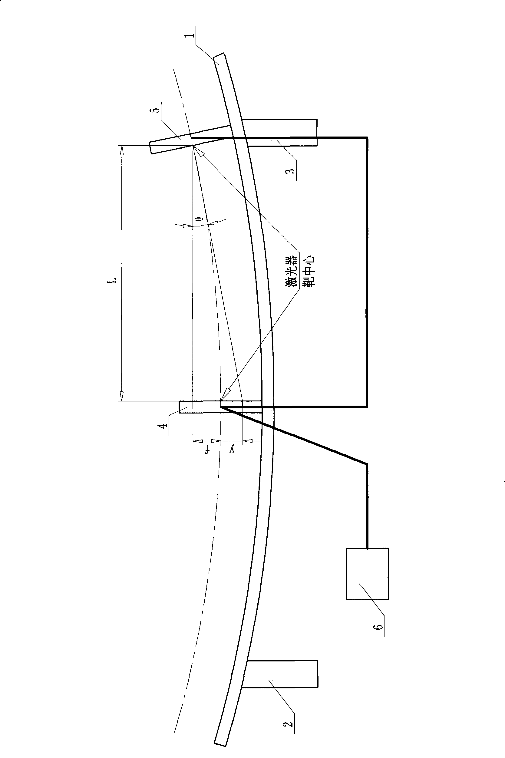
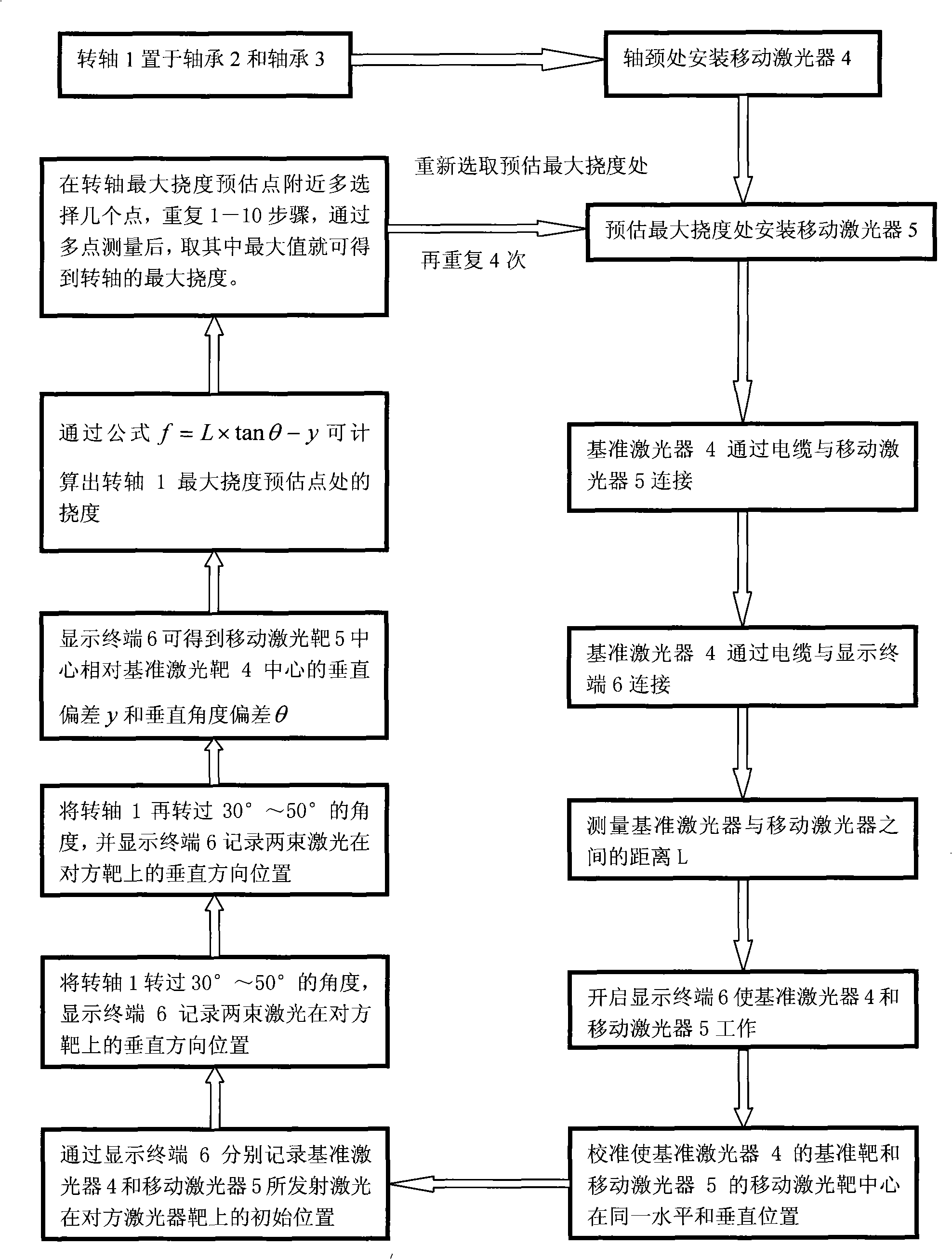
[0030] Such as figure 2 As shown, it is a schematic diagram of a method for measuring the deflection of the rotating shaft, and a method for measuring the deflection of the rotating shaft is:

[0031] The first step. supporting the first bearing 2 and the second bearing 3 at both ends of the rotating shaft 1;

[0032] The second step. Install the mobile laser 5 at the journal of the rotating shaft 1, install the reference laser 4 at the estimated point of maximum deflection of the rotating shaft, the reference laser 4 is connected with the mobile laser 5 through a cable, and the reference laser 4 is connected with the display terminal 6 through a cable, And measure the distance L=680mm between the reference laser 4 and the moving laser 5, the reference laser 4, the moving laser 5 and the display terminal 6 are all outsourced;

[0033] The 3rd step. assembly language programming, run on the display terminal 6;

[0034] Step 4. Turn on the power supply of the display terminal...


PUM


Abstract

The invention relates to a method for measuring the deflection of a rotating shaft. The method is characterized in that the method comprises the following steps of: arranging a reference laser and a moving laser on a neck journal of the rotating shaft and a pre-estimated point of the largest deflection of the rotating shaft respectively; rotating the rotating shaft at two same angles based on an initial position; and recording a parallel misalignment and an angular deviation of laser on a laser target every time, so that a vertical deviation and a vertical angular deviation of the center of a moving laser target relative to the center of a reference laser target can be measured. Deflections at the pre-estimated point of the largest deflection of the rotating shaft can be indirectly calculated through a measured value, and the largest deflection of the rotating shaft can be obtained by taking the maximum value in the deflections through multi-metering. The method has the advantages of simple and convenient measurement.

Description

technical field [0001] The invention relates to a method for measuring the deflection of a rotating shaft, which can be used to measure the maximum deflection of a supported rotating shaft in a static state, and belongs to the field of measurement technology. Background technique [0002] Rotating shafts are widely found in rotating machinery such as electric motors, such as turbine generator rotors. [0003] With the increase of unit capacity, the rotor of the turbogenerator is getting longer and more flexible, and it is more necessary to measure the deflection of the rotor of the horizontal two-pole turbogenerator due to its own weight. [0004] In the past, jacks and dial gauges were used to measure rotor deflection on lathes. The measurement was very troublesome. The bigger problem was that when the force of the jack reached a certain value, if there was a deviation in the adjustment, the bearing seat would fall out of the air and the rotor would fall. Contents of the ...

Claims


Application Information

Patent Timeline
IPC IPC(8): G01M5/00G01M13/04
Inventor 姚金传张燕耿文骥黄兆款孙家旸
Owner SHANGHAI ELECTRIC POWER GENERATION EQUIPMENT CO LTD
Why Eureka
Try Eureka