Boot for universal joint

A universal coupling and dust cover technology, applied in the field of dust cover, can solve the problems of increased contact surface pressure, increased operating torque, wear, etc., to reduce rotational resistance, inhibit the increase of contact force, The effect of reducing durability

Inactive Publication Date: 2012-02-01
NOK CORP +1
View PDF2 Cites 0 Cited by
  • Summary
  • Abstract
  • Description
  • Claims
  • Application Information

AI Technical Summary

Problems solved by technology

Therefore, when the angle of the coupling (the angle of the rotating shaft 203 relative to the rotating shaft 202) is relatively large, as in Figure 9 As shown in the lower part of , in the half cycle when the bellows part 101 is compressed, the mountain-shaped parts 101a, 101c, 101e and the valley parts 101b, 101d are all in contact with each other, but the pressure on the contact surface increases, so the resistance to rotation Increasing the operating torque will also increase, and there will be a possibility of early wear

Method used


Image

  • Boot for universal joint
  • Boot for universal joint
  • Boot for universal joint

Examples


Embodiment

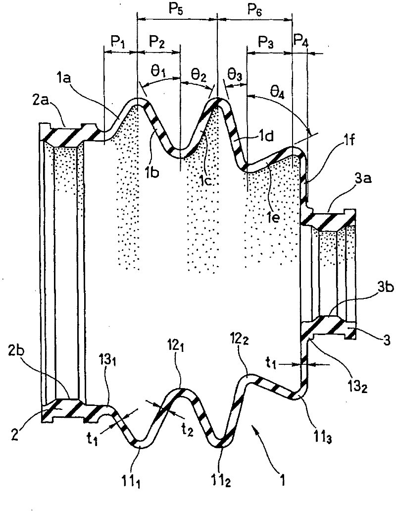
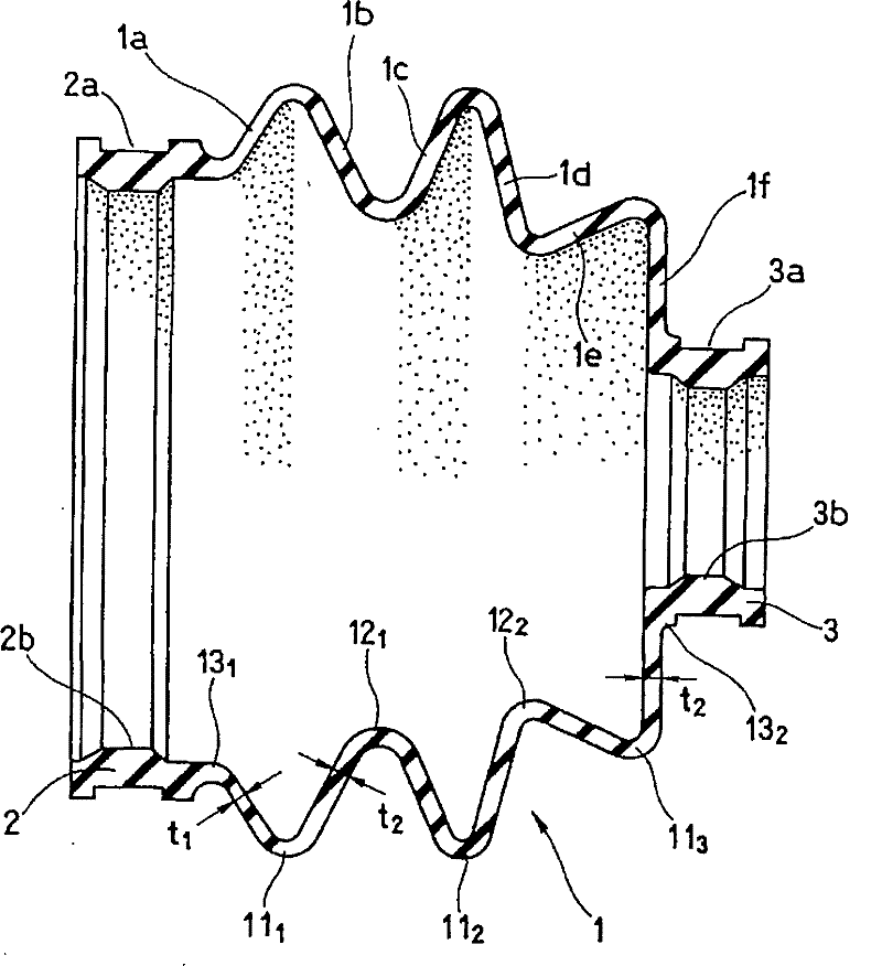
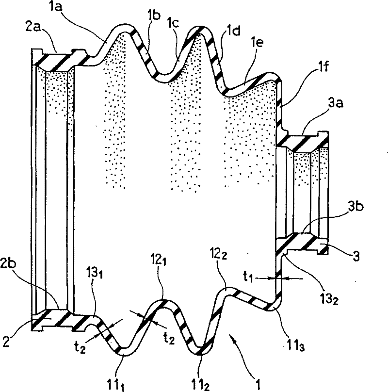
[0054] Table 1 represents the pair with figure 1 The dustproof cover and installation shape, installation size and set length of the embodiment of the present invention with the same structure shown are all the same as this embodiment, but the wall thickness of the bellows part 1 is uniform (all are t 2 ) and θ 1 = θ 2 , θ 3 = θ 4 Compared with the dust boots of the comparative example, when the coupling angle increases, the valley portion 12 on the side where the bellows part 1 is compressed 1 Between the sides and in the valley 12 2 The result of the angle at which contact begins between the two sides. It can be seen from Table 1 that the dust cover according to the present invention greatly delays the timing at which the compression side starts to contact.

[0055] Table 1

[0056]

[0057] Figure 4 is denoted by FEM derivation of the coupling angle with valley 12 1 The result of the contact force relationship between the two sides is an explanatory diagram co...


PUM


Abstract

A bellows section (1) of a boot is adapted to be flexibly and repeatedly deformable without reduction in durability, thereby rotational resistance when a joint angle is large is reduced. The boot has the bellows section (1) in which three or more circumferentially extending crests (111-113) and roots (121-122) between the crests are repeatedly formed; a large diameter installation section (2) formed at one end of the bellows section; and a small diameter installation section (3) formed at the other end. In the bellows section (1), a rising wall (1a) closest to the large diameter installation section (2) and a rising wall (1f) closest to the small diameter installation section (3) have smaller wall thickness than other portions of the bellows section (1). The ratio (t1 / t2) of the thickness (t1) of the rising walls (1a, 1f) to the thickness (t2) of the other portions of the bellows section (1) is set to 0.6 = t1 / t2 < 1.0.

Description

technical field [0001] The present invention relates to a dust cover that is installed in a universal joint such as a constant velocity joint (CVJ) such as a drive shaft of an automobile and that seals the universal joint. Background technique [0002] Constant velocity couplings such as drive shafts of automobiles are sealed with dust covers to prevent internal grease leakage or muddy water or dust from entering from the outside. Figure 8 It is a partially cutaway side view showing such a universal joint dust cover 100 together with a constant velocity joint 200, Figure 9 is expressed in Figure 8 The dust cover 100 for the universal joint shown in is a cross-sectional view showing together with a part of the constant velocity joint 200 in a deformed state. [0003] exist Figure 8 The dust cover 100 shown in is formed by blow molding or injection molding of a rubber-like elastic material, etc., and consists of a plurality of mountain-shaped portions 101a, 101c, 101e exte...

Claims


Application Information

Patent Timeline
Patent Type & Authority Patents(China)
IPC IPC(8): F16D3/84
CPCF16D3/845F16J3/041
Inventor 佐藤宽之山崎健太石岛实
Owner NOK CORP
Why Eureka
Try Eureka