

Rail lofting ruler and measuring locating device thereof
A technology for positioning equipment and rails, which is applied to rails, measuring instruments, rail maintenance and other directions, can solve the problems of inability to determine the specific position and line direction of the rails, and inability to directly realize the lofting function, and achieve the effect of good market prospects.
- Summary
- Abstract
- Description
- Claims
- Application Information
AI Technical Summary
Problems solved by technology
Method used
Image

Examples
Embodiment Construction
[0012] The present invention will be further described below in conjunction with accompanying drawing.
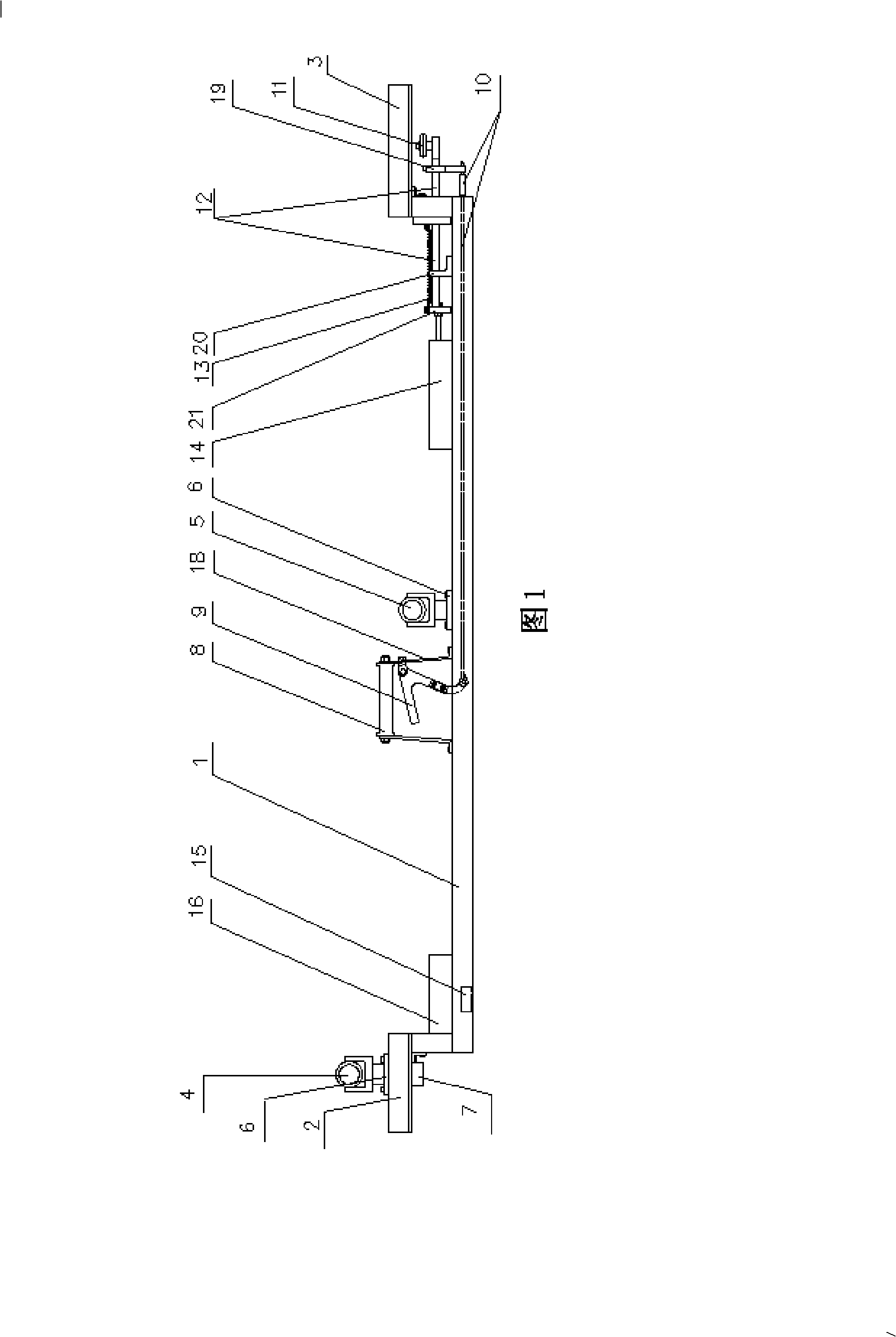
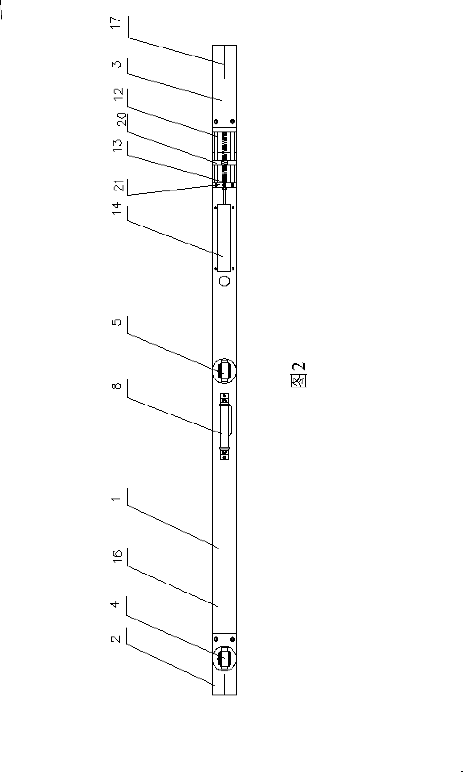
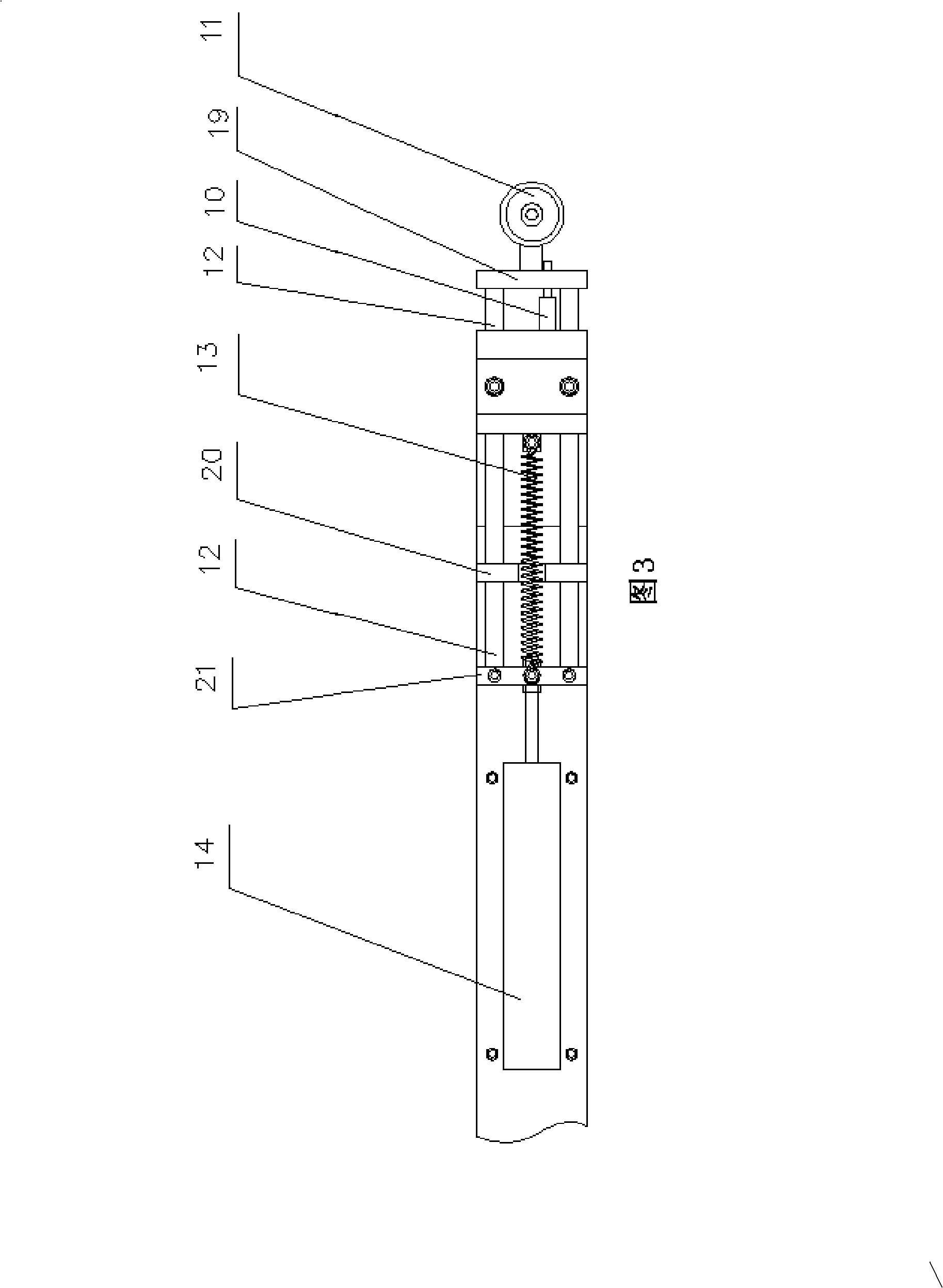
[0013] As shown in Fig. 1, Fig. 2 and Fig. 3, the present invention mainly consists of main beam 1, left rail beam 2, right rail beam 3, rail top prism 4, center prism 5, tight pulley 7, brake handle 9, pull rod 10 , Measuring wheel 11, measuring wheel support bar 12, extension spring 13, gauge sensor 14, inclination sensor 15 and electrical control box 16 are made up.
[0014] The left rail beam 2 and the right rail beam 3 are processed into a whole with the main beam 1, the rail top prism 4 and the center prism 5 are respectively inserted in the respective prism holders 6, and the rail top prism 4 and the tight wheels 7 are respectively arranged on the left rail beam On the upper and lower sides of 2, the rail top prism 4 is located directly above the tight wheel 7 and the geometric relationship with the left rail beam 2 and the tight wheel 7 is fixed, and the geometric r...
PUM
 Abstract
Description
Claims
Application Information