Backlight module group causing display possessing stereo image-forming function and its light guide board

A technology of backlight module and light guide plate, which is applied in the direction of light guide, optics, instruments, etc., and can solve the problems of increased weight and reduced brightness of liquid crystal displays

Inactive Publication Date: 2008-10-22
INNOLUX CORP
View PDF0 Cites 28 Cited by
  • Summary
  • Abstract
  • Description
  • Claims
  • Application Information

AI Technical Summary

Problems solved by technology

However, the grating 24 added in this embodiment will filter out part of the light, reducing the brightness by about 5%.
However, a polarizing unit must be

Method used


Image

  • Backlight module group causing display possessing stereo image-forming function and its light guide board
  • Backlight module group causing display possessing stereo image-forming function and its light guide board
  • Backlight module group causing display possessing stereo image-forming function and its light guide board

Examples


Embodiment 1

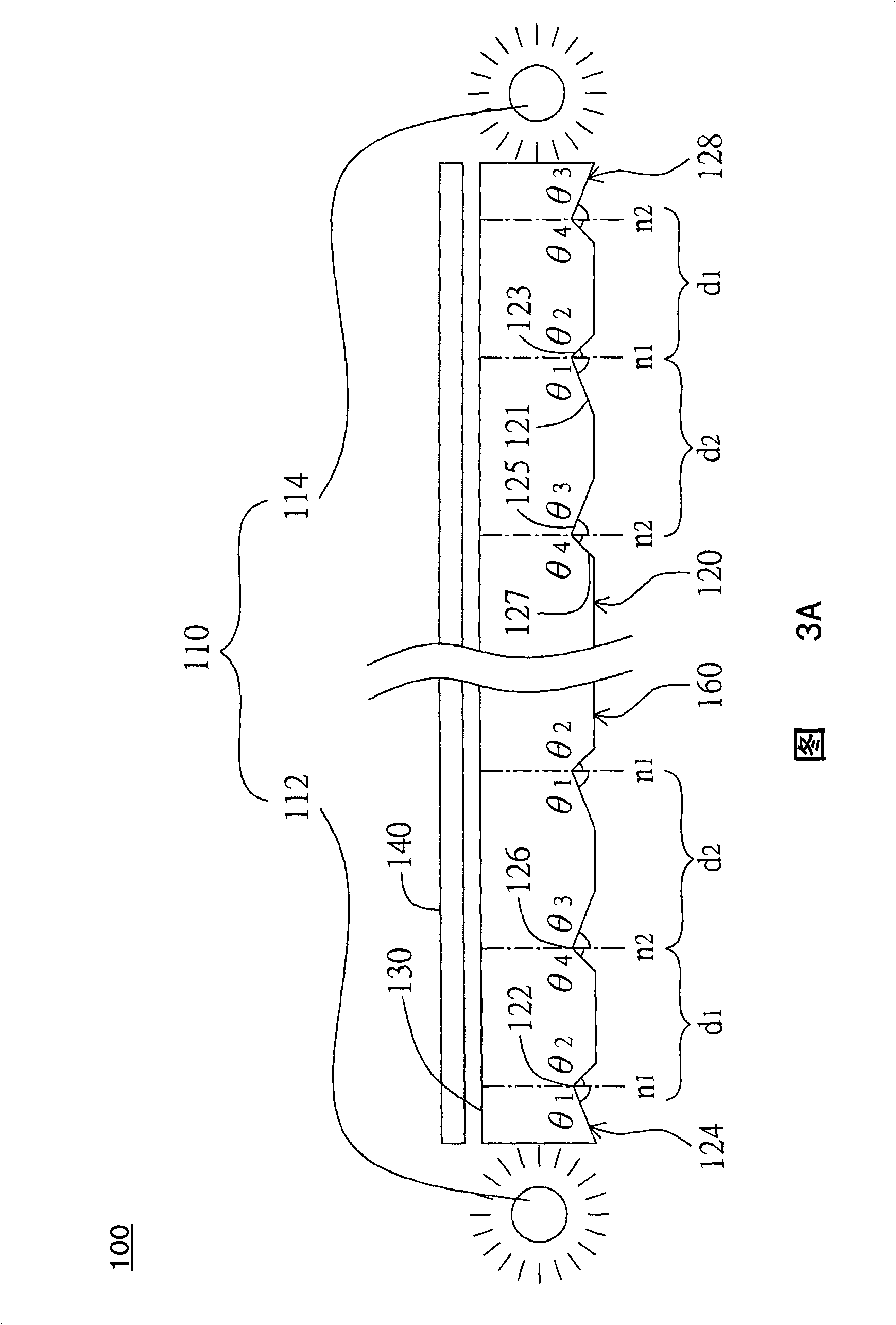
[0019] Please refer to FIG. 3A , which is a side view of a display backlight module according to Embodiment 1 of the present invention. The backlight module 100 includes a side light source group 110 , a light guide plate 120 , and preferably a prism sheet 140 . The side light source group 110 includes a first side light source and a second side light source, such as a side light source 112 and a side light source 114 , which are respectively located on the left and right sides of the light guide plate 120 , and alternately emit light to pass through the light guide plate 120 . The light guide plate 120 has a light reflection surface 160 and a light exit surface 130, and a plurality of first grooves and a plurality of second grooves are formed on the light reflection surface 160, the first grooves are, for example, grooves 124, and the second The groove is, for example, the groove 128 . Each groove 124 has a reflective surface 121 and a non-reflective surface 123, and the ref...

Embodiment 2

[0026] Please refer to FIG. 5 , which is a plan view of the light guide plate and the side light source group according to the second embodiment of the present invention. The main difference between this embodiment and the first embodiment lies in the arrangement direction of the grooves and the arrangement of the side light source groups. A side surface 250 of the light guide plate 220 intersects the extension of the intersection line 222 and the intersection line 226 to form an angle φ, and the angle φ is an acute angle, that is, the angle range is greater than 0° and less than 90°. In this embodiment, the grooves (not shown) with the intersection line 222 and the grooves (not shown) with the intersection line 226 are arranged alternately, and are mirror-symmetrical with the diagonal ψ as the axis of symmetry. The two kinds of grooves are arranged alternately, and the distance relationship between the grooves is d1>d2>d2>...>dn. The side light source 212 and the side light ...

Embodiment 3

[0028] Please refer to FIG. 6 , which is a plan view of the light guide plate and the side light source group according to the third embodiment of the present invention. The main difference between this embodiment and the first and second embodiments lies in the arrangement of the grooves and the form of the side light source group. The light guide plate 320 of this embodiment has a plurality of grooves R1 and a plurality of grooves R2. The grooves R1 and R2 are arranged alternately along the line connecting the side light source 312 and the side light source 314 . In addition, the distance d1 > d2 > d2 > . The grooves R1 and R2 are also arranged alternately along the direction parallel to the side light sources 312 / 314 , so that the grooves R1 and R2 are distributed in dots on the light guide plate 320 . The arrangement of the grooves in this embodiment enables the light guide plate 320 to reflect the light generated by the side light sources 312 and 314 more uniformly, s...


PUM


Abstract

The invention discloses a back light module which is applied to a display. The back light module comprises at least one light guide and a side light source group, wherein, the light guide is provided with a light reflecting surface, a light emergent surface, a plurality of first grooves and a plurality of second grooves; the light emergent surface is opposite to the light reflecting surface, the plurality of first grooves and the plurality of second grooves are formed on the light reflecting surface; the side light source group at least comprises a first side light source and a second side light source which are respectively arranged at opposite positions of the light guide for generating and transmitting light in the light guide. When the light generated by the side light source group is transmitted in the light guide, the first grooves and the second grooves are respectively used for reflecting the light generated by the first side light source and the second side light source and emitting the light to the light emergent surface. The first grooves and the second grooves respectively reflect the light generated by the first side light source and the second side light source independently, thereby ensuring that the display has the function of imaging three-dimensionally.

Description

technical field [0001] The present invention relates to a backlight module and its light guide plate, and in particular to a backlight module capable of displaying stereoscopic images and its light guide plate. Background technique [0002] With the advancement of signal processing and display technology, it is now possible to display stereoscopic images through flat-panel displays. The imaging principle of the stereoscopic image is mainly to generate images for the left eye and the right eye respectively, so that the left eye and the right eye of the viewer can only see the corresponding images. Since the two images have slight angle differences, it is equivalent to the viewer watching the same object with the left eye and the right eye at different angles, so the viewer's brain will mix the signals received by the left and right eyes, so that the viewer sees the same object with different angles. Stereoscopic imagery. [0003] Please refer to FIG. 1 , which is a schemati...

Claims


Application Information

Patent Timeline
IPC IPC(8): G02F1/13357G02B6/00G02B27/22G02F1/1335
Inventor 高扬民黄建智
Owner INNOLUX CORP
Why Eureka
Try Eureka