Automobile air conditioner control system air door self-calibration method
A control system and automotive air-conditioning technology, applied in the general control system, control/regulation system, adaptive control, etc., can solve problems such as motor stalling, motor aging acceleration, damper closing is not tight, etc., to enhance reliability, overcome Effects of Manufacturing and Assembly Errors
Inactive Publication Date: 2008-10-22
SHANGHAI DELCO ELECTRONICS & INSTR
View PDF0 Cites 7 Cited by
- Summary
- Abstract
- Description
- Claims
- Application Information
AI Technical Summary
Problems solved by technology
The position calibration of the damper mainly adopts the default value method. When the assembly and manufacturing accuracy of the air conditioning system is good, the default value method is simple and reliable, but when the air conditioning system assembly and manufacturing accuracy is poor, the default value method is used. Often there will be problems such as the air door is not closed tightly, or the motor is blocked, resulting in poor cooling / heating effect of the air conditioner, or the aging of the motor is accelerated, and the motor is damaged, etc.
Method used
View moreImage
Smart ImageViewing Examples
Examples
Embodiment Construction
Login to View More PUM
 Abstract
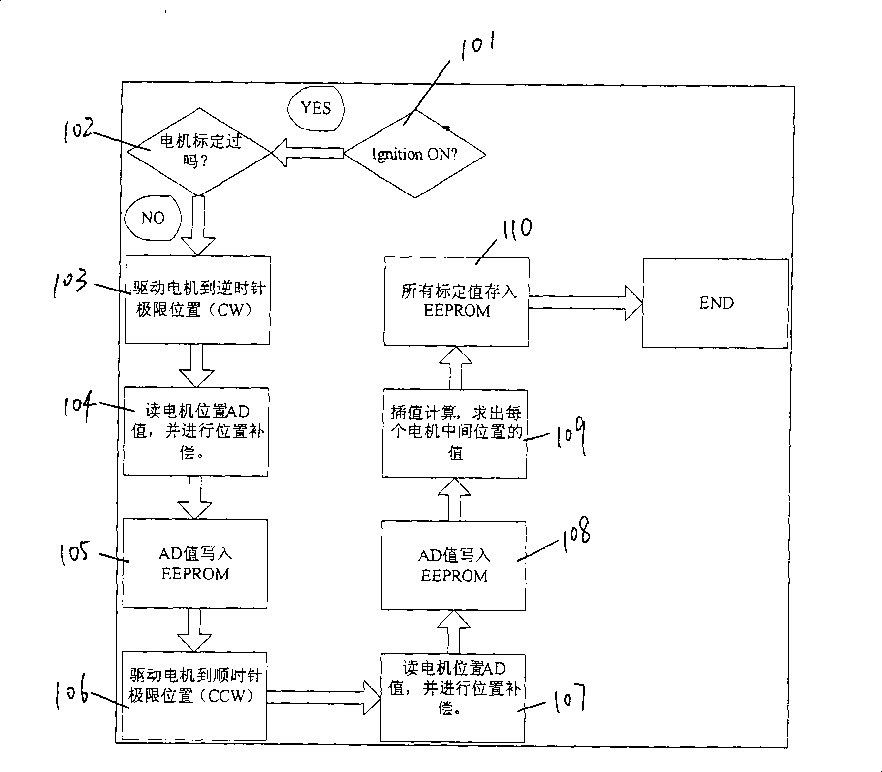
The present invention discloses an air door self-calibration method for an automobile air-conditioning control system. The method comprises the followings steps of: A. driving an air door motor to an anticlockwise limit position; B. reading the value of the anticlockwise limit position of the motor; C. writing the value of the anticlockwise limit position; D. driving the air door motor to a clockwise limit position; E. reading the value of the clockwise limit position of the motor; F. writing the value of the clockwise limit position; G. after each motor obtains two limit positions, obtaining an ideal motor calibration value at any position between the two limit positions according to the linear interpolation algorithm; H. writing the calibration value. With the method, the self- calibration strategy is adopted by the control motor with position feedback so that the production errors and assembling errors generated by the air-conditioning system are effectively overcome and the reliability of the air-conditioning system is improved.
Description
Self-calibration method for damper of automobile air-conditioning control system Technical field: The invention relates to an automobile air-conditioning control system, in particular to a self-calibrating method for a damper of the automobile air-conditioning control system. Background technique: The temperature control of the automobile air-conditioning system, the control of the air supply mode and the wind direction are mainly realized by driving the damper to different positions by the motor, such as the temperature control of the air-conditioning system, the temperature selection is realized by controlling the change of the resistance value of the potentiometer by the temperature knob, and the temperature The control is realized by controlling the motor position of the mixing damper, and different damper positions represent different temperatures. The position calibration of the damper mainly adopts the default value method. When the assembly and manufacturing accura...
Claims
Login to View More Application Information
Patent Timeline
 IPC IPC(8): G05B21/02G05B13/02
Inventor 杨毅施麟范臧铁生顾卫康龚旋
Owner SHANGHAI DELCO ELECTRONICS & INSTR
Features
- R&D
- Intellectual Property
- Life Sciences
- Materials
- Tech Scout
- Unparalleled Data Quality
- Higher Quality Content
- 60% Fewer Hallucinations
Learn More Browse by: Latest US Patents, China's latest patents, Technical Efficacy Thesaurus, Application Domain, Technology Topic, Popular Technical Reports.
© 2025 PatSnap. All rights reserved.Legal|Privacy policy|Modern Slavery Act Transparency Statement|Sitemap|About US| Contact US: help@patsnap.com

