Hydraulic lift for drive wheel of hand tractor

A technology of hydraulic lifting device and walking tractor, which is applied to the lifting device, control device, adjustment device and other directions of agricultural machinery, which can solve the problems of limited height adjustment, not compact enough structure, and affecting the balance of the body, so as to achieve convenient height adjustment and excellent structure. Compact, Possibilities-reducing Effects

Inactive Publication Date: 2008-10-29
JIANGSU ZHONGWEI HEAVY IND MACHINERY +1
View PDF2 Cites 4 Cited by
  • Summary
  • Abstract
  • Description
  • Claims
  • Application Information

AI Technical Summary

Problems solved by technology

Among the above two utility models, the utility model patent of 87217114U changes the front and rear positions of the wheels when adjusting the height of the two wheels, causing the position of the center of gravity of the machine body to change back and forth, affecting the balance of the whole machine body, which may affect the operation
The utility model patent of 200520031973.8 has poor stability when the wheels are impacted by uneven road surfaces; in addition, the gear transition transmission is used, and the adjustment height is limited. If you want to increase the adjustment height, you need to increase the gear size, and the structure is not compact enough

Method used


Image

  • Hydraulic lift for drive wheel of hand tractor
  • Hydraulic lift for drive wheel of hand tractor
  • Hydraulic lift for drive wheel of hand tractor

Examples


Embodiment

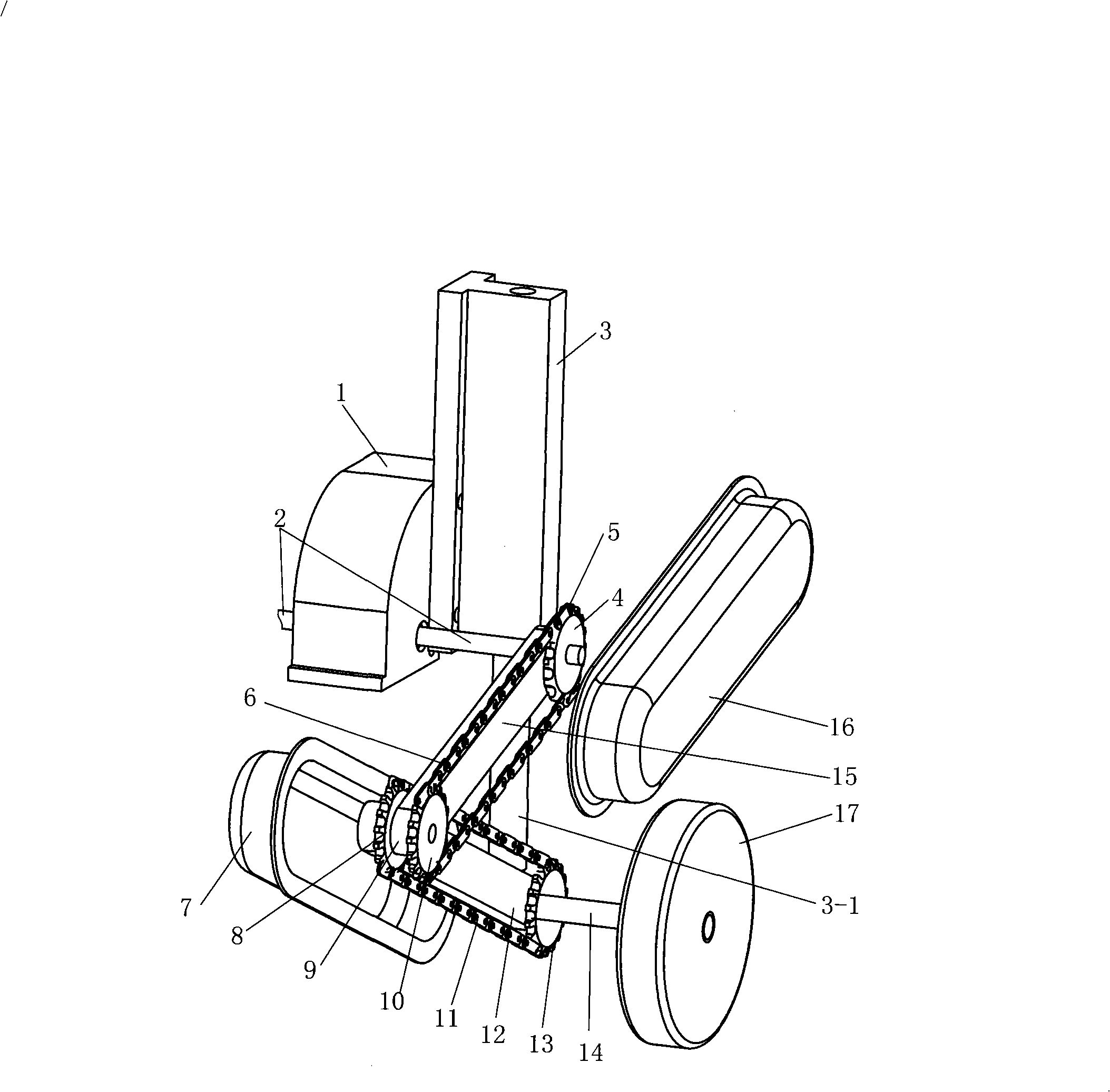
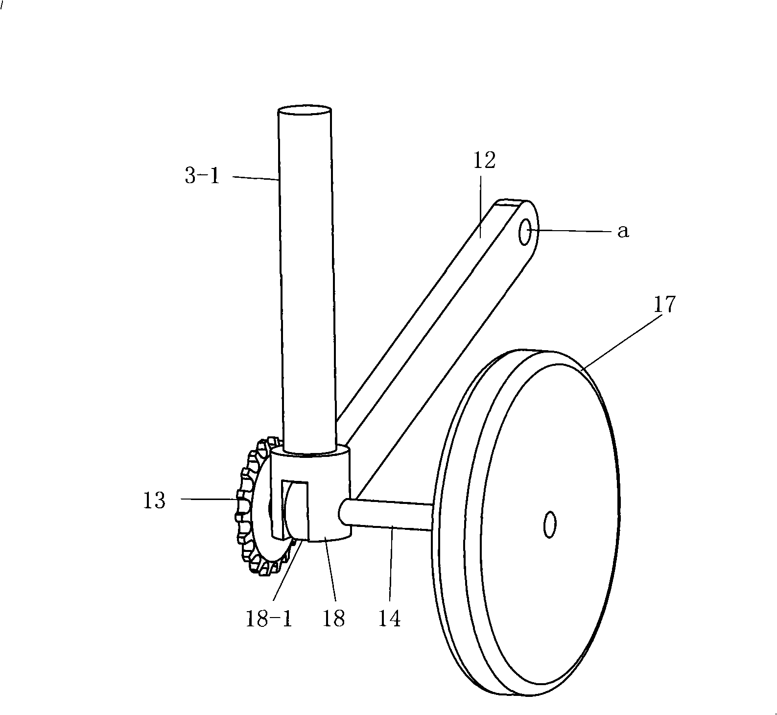
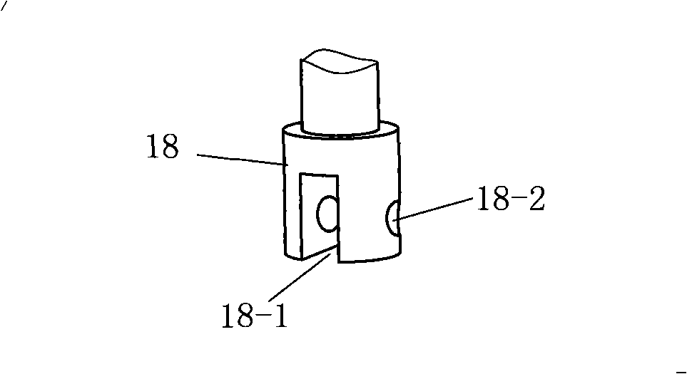
[0021] See figure 1 , the present embodiment includes a transmission case housing 1 on a common tractor and two driving axle shafts 2 respectively located on both sides of the transmission case housing 1. The structures on the left and right sides of the transmission case housing 1 are symmetrical. figure 1 The left part is omitted. Both sides of the transmission box housing 1 are respectively fixed with a hydraulic cylinder 3, and the bottom end of the piston rod 3-1 of the hydraulic cylinder 3 is provided with a connecting piece 18, and the piston rod 3-1 is dynamically connected with the driving half through the connecting piece 18. Shaft 2 is parallel to output shaft 14 . A transition shaft 9 is provided between each output shaft 14 and the drive half shaft 2 on the same side; an upper support plate 15 is provided between the drive half shaft 2 and the transition shaft 9 on the same side, and the drive half shaft 2 on the same side Chain transmission between the transiti...


PUM


Abstract

A hydraulic lifting device for driving wheels of a walking tractor comprises a transmission box housing and two drive semi-shafts; the two side surfaces of the transmission box housing are respectively and fixedly provided with a hydraulic cylinder; a piston rod of each hydraulic cylinder is movably connected with an output shaft parallel with the drive semi-shafts; a transition shaft is arranged between each output shaft and the drive semi-shaft arranged at the same side; an upper supporting plate is arranged between the drive semi-shaft and the transition shaft at the same side; besides, the drive semi-shaft and the transition shaft are in chain transmission at the same side; a lower supporting plate is arranged between the transition shaft and the output shaft arranged at the same side; besides, the transition shaft and the output shaft arranged at the same side are in chain transmission; the two driving wheels of the tractor are respectively mounted on the two output shafts; when the invention is used for adjusting the heights of the two wheels, the front position and the back position of the left driving wheel and the right driving wheel can be maintained to be changeless, thus leading the positions of the front gravity center and the back gravity center of a machine body to be maintained to be changeless, thereby ensuring the balance of the whole machine body. The device of the invention adopts sprocket drive, which has the advantages of high adjusting height relative to gear transmission and compact structure.

Description

technical field [0001] The invention relates to a hydraulic lifting device for driving wheels of a walking tractor. Background technique [0002] At present, many agricultural machinery use walking tractors as power sources, and are equipped with various equipment such as rotary tillage, soil breaking, sowing, planting, and digging to realize mechanized operations. The walk-behind tractor has a transmission box, and two driving half-shafts stretch out from both sides of the transmission box respectively, and two driving wheels are installed on the two driving half-shafts respectively, and the height of the two driving wheels cannot be adjusted. In order to realize the operation of the traveling tool on the slope, the height of the two drive wheels needs to be adjusted, so the existing walking tractor cannot work on the slope. At present, operations in slope areas such as mountains and hills are still done manually. Chinese patent application number is 87217114U utility mod...

Claims


Application Information

Patent Timeline
Patent Type & Authority Applications(China)
IPC IPC(8): B60K17/32A01B63/00
Inventor 孙奎洲
Owner JIANGSU ZHONGWEI HEAVY IND MACHINERY
Why Eureka
Try Eureka