Deep foundation pit steel reinforced concrete fender post, producing and embedding method thereof

A technology of reinforced concrete and retaining piles, which is applied in the direction of manufacturing tools, sheet pile walls, and foundation structure engineering. It can solve problems such as unreasonable cross-sections and reinforcements, pollute the environment, and waste materials, so as to facilitate manufacturing and speed up construction. Speed, friction reduction effect

Inactive Publication Date: 2008-10-29
杨峰
View PDF0 Cites 9 Cited by
  • Summary
  • Abstract
  • Description
  • Claims
  • Application Information

AI Technical Summary

Problems solved by technology

[0003] The present invention aims to solve the problems of material waste, high cost, and environmental pollution by using bored cast-in-place piles for the protection piles of deep foundation pits, as well as the difficulties in making, transporting and constructing the whole reinforced concrete T-shaped piles, cross-section and reinforcement. Unreasonable problem, provide a kind of deep foundation pit reinforced concrete enclosure pile of the present invention for this reason, the manufacture and embedding method of this pile, this kind of pile can save more than 60% of steel material, save concrete 50% compared with cast-in-place pile %, the cost is reduced by more than 50%, and the manufacturing is convenient, the construction speed is fast, and the impact on the surrounding environment is small

Method used


Image

  • Deep foundation pit steel reinforced concrete fender post, producing and embedding method thereof
  • Deep foundation pit steel reinforced concrete fender post, producing and embedding method thereof
  • Deep foundation pit steel reinforced concrete fender post, producing and embedding method thereof

Examples


Embodiment 1

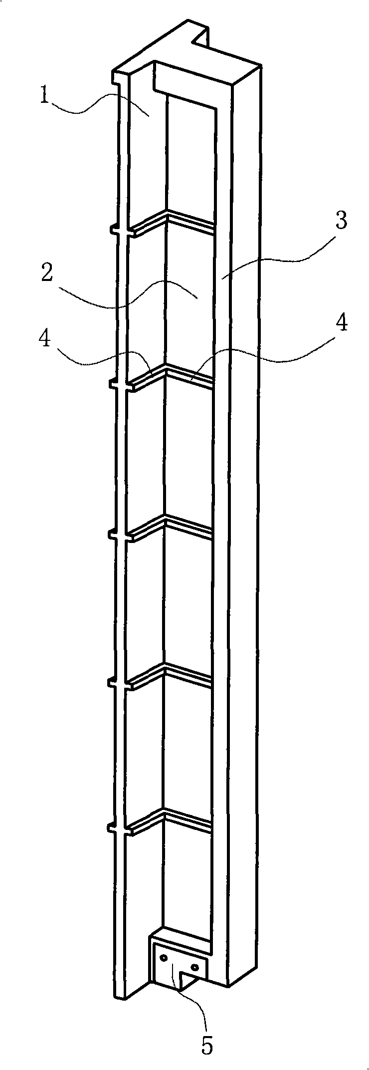
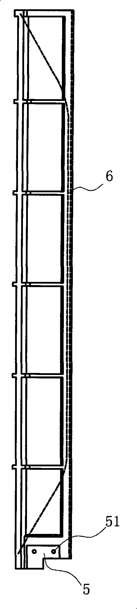
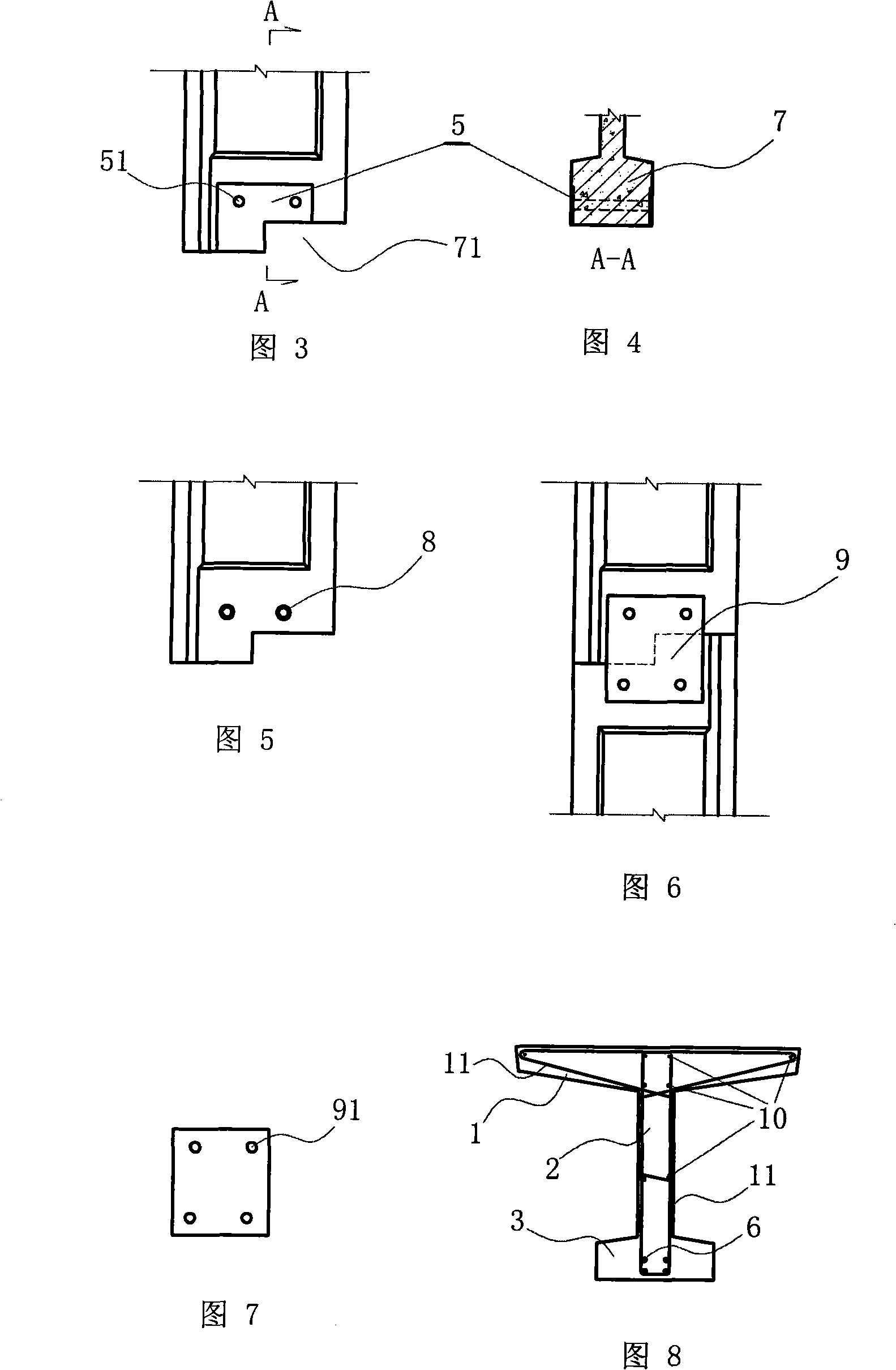
[0040] A reinforced concrete enclosure pile for a deep foundation pit has a web 2, a flange I1 is connected to one side of the web, and a flange II3 with a width smaller than the flange I is connected to the other side of the web, the web and the flange I is vertically provided with steel bars 10, and the web at one end of the pile body has a thickened section 7, and this thickened section is provided with a connecting fixture, which is: embedded in the thickened section parallel to the thickened The length in the thickness direction of the section is equivalent to the steel pipe 8 with the thickness of the thickened section; a non-prestressed steel strand 6 is longitudinally embedded in the other side of the web, and the non-prestressed steel strand is also located in the middle of the flange II3. The two ends of the stranded wire are inwardly bent and extend to the flange I; ribs 4 are provided at intervals on the web and the flange.

Embodiment 2

[0042]A method for manufacturing and embedding reinforced concrete enclosure piles for deep foundation pits, including tying steel reinforcement cages, supporting formwork, pouring concrete, demoulding, raising houses, pressing piles, and transporting piles, and the tying steel reinforcement cages are combined Reinforcement cage, the combined reinforcement cage is made of a thickened section with a gap 71 at one end of the web-shaped cage part, the flange I1-shaped cage part and the web-shaped cage part 7. Combined combined reinforcement cage of the cage part, the notch 71 of the cage part of the thickened section is a notch towards the end face of the cage part of the thickened section and the direction facing away from the flange I1-shaped cage part, said The flange I1-shaped cage part of the combined reinforcement cage is connected to one side of the web 2-shaped cage part, and the web 2-shaped cage part and the flange I1-shaped cage part are provided with corresponding stir...

Embodiment 3

[0044] The manufacturing and embedding method of reinforced concrete retaining piles for deep foundation pits in this example is different from Example 2 in that the integral translational side form described is made of all-steel structure and can be placed on the ground to support formwork or be removed freely. The side form of the mould, the main frame inside the side form is made into a groove-shaped main frame 131, and this groove-shaped main frame doubles as a web 2 convex edge mold so that the web has a convex edge 4, and the gap between the opposite side molds The upper brace is made into a groove-shaped brace 12, and this groove-shaped brace doubles as a flange I1 rib mold so that the flange I has a rib 4; other steps are the same as those of Example 2, and in addition, when the pile is pressed, the Mud or water is injected into the gap between the convex rib and the soil and the pile body to reduce the friction resistance between the pile body and the soil layer when t...


PUM


Abstract

The invention provides a deep foundation pit reinforced concrete supporting pile. One side of a web is connected with a flange I, a thickened section is arranged at one end of the web, a connecting and fixing part is arranged on the thickened section, and a steel strand is internally and vertically buried on the other side of the web. The manufacturing and the installing methods of the deep foundation pit reinforced concrete supporting pile include the steps as follows: a combined steel reinforcement cage composed of a web-shaped cage body part, a flange I-shaped cage body part and a thickened section cage body part arranged at one end part of the web-shaped cage body part is formed, the web-shaped cage body part is vertically provided with the steel strand on one side, and the thickened section cage body part is provided with the connecting and fixing part. A combined form composed of a monolithic moving side form and a fixed bottom form is adopted, and the deep foundation pit reinforced concrete supporting pile with the web and the flange I is made through pouring concrete after the combined steel reinforcement cage is positioned into the combined form; a connecting plate with two ends opened with through holes is made; a pile driver is used for pressing the first pile into the ground in a way that the thickened section faces upwards, when the top end is close to the ground, the second pile is abutted with the first pile through the connecting plate in a manner that the thickened section faces downwards and the flange I faces upwards, so as to press the second pile into the ground.

Description

technical field [0001] The invention relates to a deep foundation pit support pile in a basement of a building and a manufacturing and embedding method thereof. Background technique [0002] Deep foundation pit support is a relatively complex engineering technology in construction engineering. In the construction of deep foundation pits in soft soil areas, the support method of enclosure piles plus supports or anchor rods is generally used. The most widely used enclosure piles are Bored cast-in-situ piles, although this type of pile has the advantages of convenient construction, safety and reliability, and little impact on the surrounding environment, but its section form as a bending member is very unreasonable, and the waste of materials is serious; and this type of pile is used in pile construction. A large amount of mud produced pollutes the environment, and the cost of mud discharge is high, so the overall cost is high. Prefabricated reinforced concrete special-shaped ...

Claims


Application Information

Patent Timeline
Patent Type & Authority Applications(China)
IPC IPC(8): E02D5/10E02D7/20B28B23/02
Inventor 杨峰
Owner 杨峰
Why Eureka
Try Eureka