

Floating type checking platform
A floating platform and floating technology, applied in the direction of mechanical diameter measurement, etc., can solve the problems of reduced calibration accuracy and unreasonable structural design, and achieve the effects of improved detection accuracy, simple structure, and light weight
Inactive Publication Date: 2008-10-29
严为民
View PDF0 Cites 2 Cited by
- Summary
- Abstract
- Description
- Claims
- Application Information
AI Technical Summary
Problems solved by technology
In the existing metering and testing device, the object to be tested is fixed and cannot float, and the micrometer element is floating, but the micrometer element can only perform one-way micrometer measurement instead of two-way micrometer measurement during the floating calibration and detection process. Unreasonable structural design, resulting in greatly reduced calibration accuracy
Method used
View moreImage
Smart ImageViewing Examples

Examples
Embodiment Construction
Login to View More PUM
 Abstract
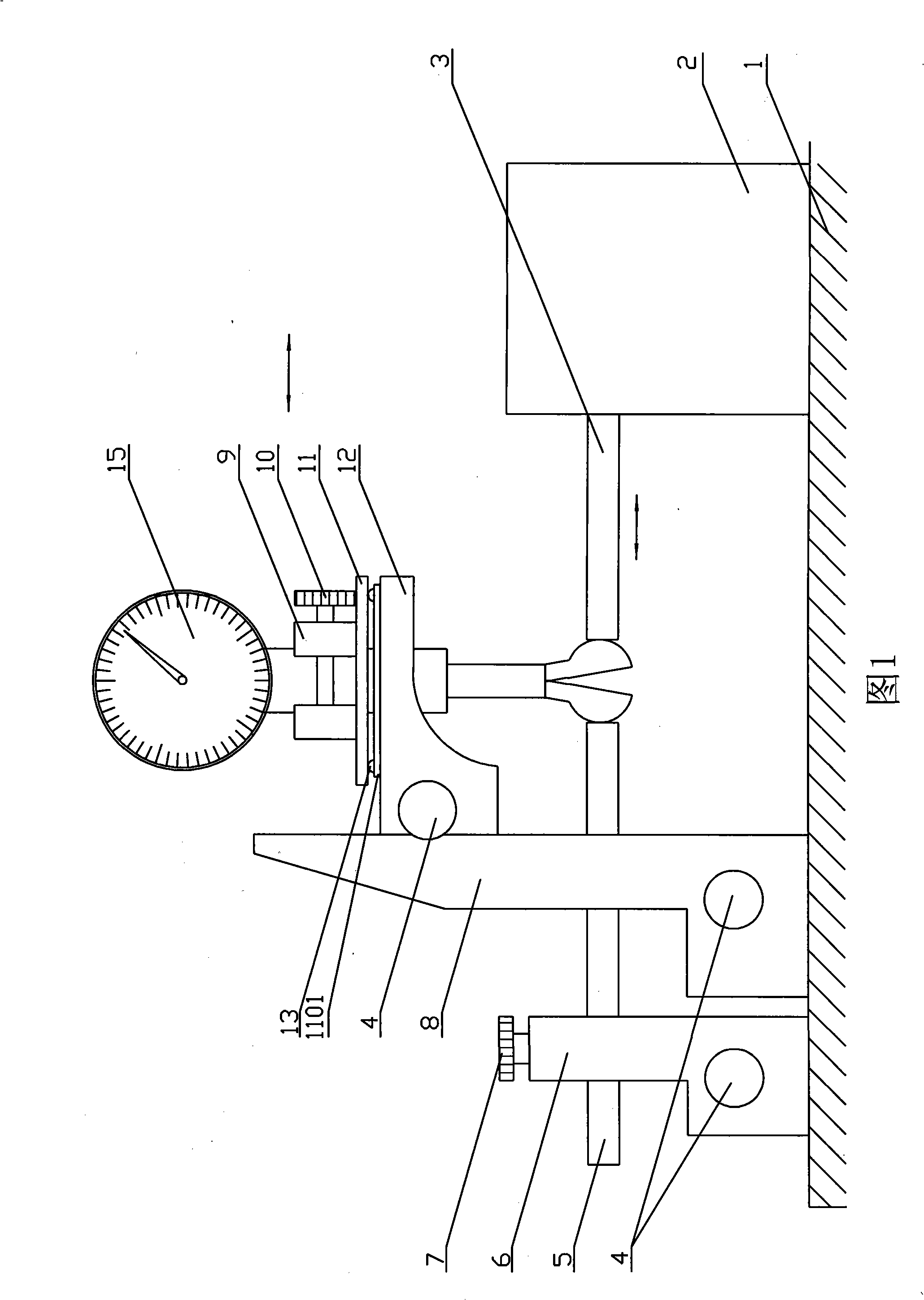
The invention relates to a floating type checking platform. A measuring element body, a mandril fixture and a floating workbench fixture are arranged on a pedestal of the checking platform. Measuring heads of the measuring element move horizontally under the control of the measuring element body, a mandril is tightly fixed on the mandril fixture, a floating workbench is tightly fixed on the floating workbench fixture, a measurand tightening fixture is arranged on the floating workbench, and a floating platform is fixedly connected with the bottom of the measurand tightening fixture, so that the measurand fixture can relatively and parallelly move by a force which is absolutely smaller than the floating thrust force and the acting force of an micrometering element, and the detection requirements which the measurands have equal size, opposite direction and bi-directional stress are satisfied by a uni-directional floating thrust force of the micrometering element and the parallel relative movement of the floating checking platform, thus effectively improving the accuracy of correction and measurement. The checking platform has simple structure, small size, light weight, high accuracy and easy operation, and is applicable to a DS series grating indicating gauge comparator and also widely applicable to internal or bi-directional measuring instruments, and correction and measurement on the floating platform of other high-accuracy measurands which require bi-directional stress measurement.
Description
Floating inspection platform technical field The invention belongs to the field of measuring instrument testing devices, and relates to a floating checking platform. Background technique In the existing metering and testing device, the object to be tested is fixed and cannot float, and the micrometer element is floating, but the micrometer element can only perform one-way micrometer measurement instead of two-way micrometer measurement during the floating calibration and detection process. The structural design is unreasonable, thus causing the calibration accuracy to be greatly reduced. Contents of the invention The purpose of the present invention is to provide a floating calibration platform with simple structure, reasonable design and effective improvement of calibration accuracy. The technical scheme adopted in the present invention: a floating calibration platform, the base of which is provided with a measuring element body, a plunger clamp and a floating workta...
Claims
Login to View More Application Information
Patent Timeline
 Patent Type & AuthorityApplications(China)
IPC IPC(8): G01B5/12
Inventor田龙元
Owner严为民