Voltage regulating circuit and method for providing regulated output voltage

A voltage stabilizing circuit and output voltage technology, which is applied in the voltage stabilizing circuit and used to provide the field of regulated output voltage to achieve the best voltage stabilizing effect

Active Publication Date: 2008-10-29
MEDIATEK INC
View PDF3 Cites 18 Cited by
  • Summary
  • Abstract
  • Description
  • Claims
  • Application Information

AI Technical Summary

Problems solved by technology

Although the regulator loop can quickly discharge the initial output voltage, this regulator still suffers from the same problems described above

Method used


Image

  • Voltage regulating circuit and method for providing regulated output voltage
  • Voltage regulating circuit and method for providing regulated output voltage
  • Voltage regulating circuit and method for providing regulated output voltage

Examples


Embodiment Construction

[0017] Certain terms are used in the description and claims to refer to particular elements. Those skilled in the art should understand that hardware manufacturers may use different terms to refer to the same component. The specification and claims do not use the difference in name as a way to distinguish components, but use the difference in function of components as a criterion for distinguishing. The "comprising" mentioned throughout the specification and claims is an open term, so it should be interpreted as "including but not limited to". In addition, the term "coupled" herein includes any direct and indirect means of electrical connection. Therefore, if it is described that the first device is coupled to the second device, it means that the first device may be directly electrically connected to the second device, or indirectly electrically connected to the second device through other devices or connection means.

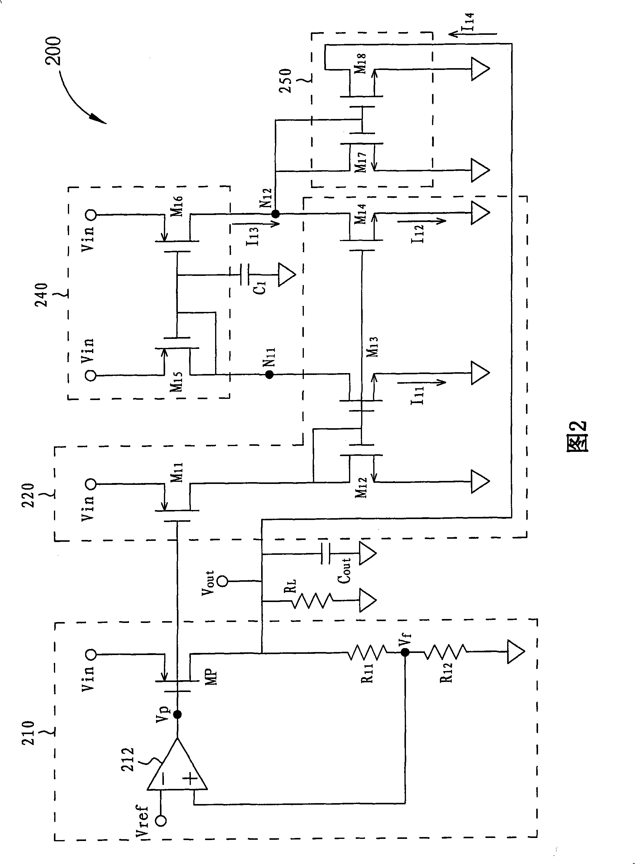
[0018] FIG. 2 is a circuit diagram of a linear voltage ...


PUM


Abstract

A voltage regulating circuit for providing a regulated output voltage. The voltage regulating circuit includes a voltage regulator, a converting circuit, a capacitive device, a first current mirror module, and a second current mirror module. The voltage regulator has a first output producing the regulated output voltage and a second output producing a pass voltage. The converting circuit converts the pass voltage into a first current and a second current passing through a first converting node and a second converting node respectively, where the first current charges/discharges the capacitive device. The first current mirror module has a first current mirror path coupled to the first converting node and a second current mirror path coupled to the second converting node.; The second current mirror module has a first current mirror path coupled to the second converting node and a second current mirror path coupled to the first output.

Description

technical field [0001] The present invention generally relates to voltage regulation, especially to a linear voltage regulating circuit and method thereof capable of minimizing undershoot effects, and more particularly to a A voltage stabilizing circuit and a method for providing a regulated output voltage. Background technique [0002] A voltage regulator coupled between a voltage supply source and a load device is often used to provide a sufficiently stable output current to maintain the driving capability of the load device. When the load device encounters rapid load current changes, that is, when the current draw or load impedance varies between large loads and small loads, conventional voltage regulators have some disadvantages. FIG. 1 shows such a conventional voltage regulator 100 in the prior art. When the load device encounters a rapid change between a large load and a small load, the prior art voltage regulator 100 will generate an undershoot problem. This volta...

Claims


Application Information

Patent Timeline
Patent Type & Authority Applications(China)
IPC IPC(8): G05F1/571
CPCG05F3/262G05F1/571G05F1/575
Inventor 陈弘易楼志宏
Owner MEDIATEK INC
Why Eureka
Try Eureka