Rectifier voltage stabilizer for mixed power vehicle

A technology for a hybrid electric vehicle and a voltage stabilizer, which is applied in the field of rectifier voltage stabilizers, can solve the problems of electronic voltage stabilizer temperature rise, the use performance needs to be further improved, energy waste and other problems

Inactive Publication Date: 2006-07-26
SHANDONG UNIV OF TECH
View PDF1 Cites 0 Cited by
  • Summary
  • Abstract
  • Description
  • Claims
  • Application Information

AI Technical Summary

Problems solved by technology

The present invention adopts the principle of random release of parallel controllable external resistance energy, and is mainly composed of five parts: load current detection circuit, control switch, threshold voltage control circuit, power switch, and power resistor. The random discharge method of resistance energy wastes energy, and the temperature of the electronic voltage regulator rises, and its performance needs to be further improved

Method used


Image

  • Rectifier voltage stabilizer for mixed power vehicle
  • Rectifier voltage stabilizer for mixed power vehicle

Examples


Embodiment Construction

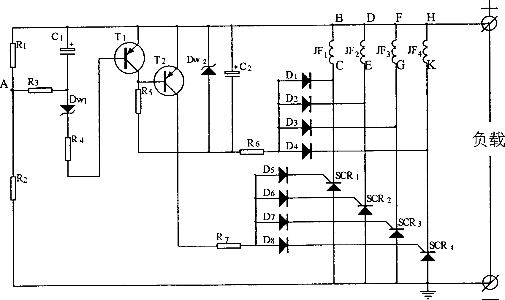
[0013] Example: R 1 , R 2 , R 3 , R 4 , R 5 , R 6 , R 7 Resistance; C 1 、C 2 Capacitance; D 1 、D 2 、D 3 、D 4 、D 5 、D 6 、D 7 、D 8 Diode; D w1 、D w2 Zener tube; T 1 , T 2 Transistor; SCR 1 、SCR 2 、SCR 3 、SCR 4 SCR; JF 1 、JF 2 、JF 3 、JF 4 The four identical coil windings of the alternator; point A is the resistor R 1 , R 2 , R 3 The junction; B is the first coil winding JF 1 The head end, C is the first coil winding JF 1 The tail end, D is the second coil winding JF 2 The head end, E is the second coil winding JF 2 The tail end, F is the third coil winding JF 3 G is the end of the third coil winding JF3, H is the fourth coil winding JF 4 The head end, K is the fourth coil winding JF 4 end of .

[0014] The present invention will be further described below in conjunction with accompanying drawing:

[0015] The rectifier circuit is a four-phase half-wave rectifier circuit, composed of the first thyristor SCR 1 , the second thyristor SCR 2 , th...


PUM


Abstract

The rectifying voltage regulator for mixed power vehicle includes reference circuit, sample circuit, trigger circuit and rectifier circuit, and the sample circuit has input connected to the reference circuit and the voltage output of generator and output connected via the trigger circuit to the rectifier circuit. The present invention features the rectifier circuit including 4 SCR's, SCR1-4, and 8 diodes, D1-8; SCR1-4 with anodes connected together, cathodes connected separately to the tail ends of 4 windings, JF1-4, of the permanent magnetic AC generator and separately via D5-8 to the trigger circuit; and the windings, JF1-4, in phase difference of 90 deg and with four first ends connected in '+' connection to one point. The present invention samples directly from the voltage output of the four-phase permanent magnetic generator and the output voltage is converted into stable DC voltage to drive the power consumers or to charge the accumulator.

Description

technical field [0001] The invention provides a rectifier voltage stabilizer for a hybrid electric vehicle, which belongs to the technical field of automobile motors and electrical appliances. Background technique [0002] The output voltage of the permanent magnet alternator changes with the speed change. The output voltage is low when the speed is low, and the output voltage is high when the speed is high. In order to make the output voltage relatively stable, in the existing technology, mechanical resistance method, electronic Short-circuit method, electronic series method, parallel controllable external resistance energy random discharge method and other voltage stabilization measures. Such as the invention patent announced on December 7, 1988 in the Chinese Patent Gazette: permanent magnet alternator electronic voltage regulator, application number: 88105250.8, which is mainly used for automatic stabilization of the output voltage of permanent magnet alternator for vehi...

Claims


Application Information

Patent Timeline
Patent Type & Authority Patents(China)
IPC IPC(8): H02P9/30
Inventor 张学义
Owner SHANDONG UNIV OF TECH
Why Eureka
Try Eureka